Inside the Type 146 Unit Cha
ter Three: Overview
70
The male connector carries open, close, manual, and set point recipe select digital control lines.
It also carries the analog set point input. Table 25, page 70, lists the pinout of this connector.
Table 28, page 71, lists MKS flow controllers that interface to the 146 unit.
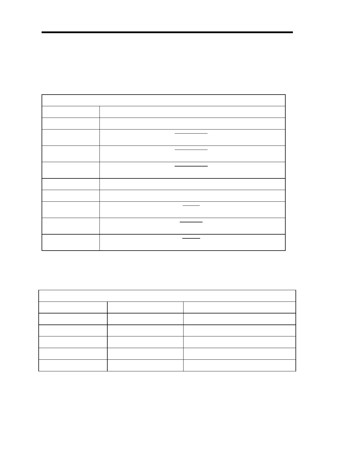
Control Interface (Bottom) Connector Pinout
Pin Number Assignment
1 Analog Set Point + (signal)
2
Set Point B
3
Set Point C
4
Set Point D
5 Digital Ground
6 Analog Set Point - (return)
7
Open
8
Manual
9
Close
Table 25: Control Interface (Bottom) Connector Pinout
Control Board Pin Jumpers
Jumper Pack Voltage/Current Jumpered For. . .
JP1 200 mA 154 valve
JP2 reserved
JP3 140 mA 148, 153, and 248 valves
JP4 26 Volts 154 valve
JP5 14 Volts 148, 153, and 248 valves
Table 26: Control Board Pin Jumpers
Artisan Technology Group - Quality Instrumentation ... Guaranteed | (888) 88-SOURCE | www.artisantg.com