How To Perform Sensor Calibration/MFC Setup Cha
ter Seven: O
eration in Setu
Mode
192
Capacitance Manometer
Torr
CLOSE
SETUP
TORR
SENSOR CAL
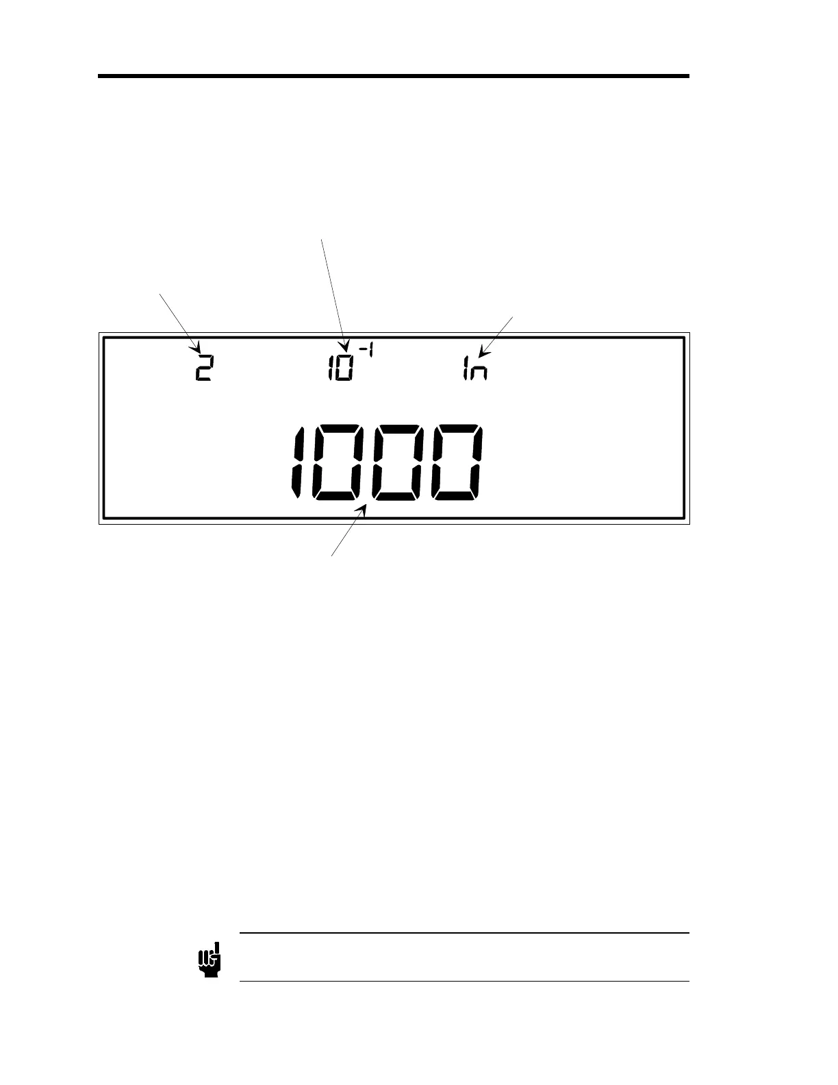
The number for the input
channel is entered here.
In this example, channel 2
is selected as the input
channel.
This display shows the
sensor resolution.
This indicates the type of
gauge associated with the
selected input channel.
Capacitance manometers
may be indicated by 107,
120, or ln (as in this case).
This is the sensor range for the capacitance
manometer on the selected input channel.
LEFT DISPLAY
CENTER DISPLAY RIGHT DISPLAY
MAIN DISPLAY
Figure 56: Sensor Calibration for Capacitance Manometers
Refer to
How To Perform Sensor Calibration/MFC Setup
, page 190, for steps 1 through 3.
Capacitance manometers may be listed as
107, 120
or
ln
in the right display.
4. Enter the span for the sensor in the main display.
The span range is
Type 107
: 940 to 1060 Torr.
Type 120 or linear capacitance manometer:
0.0009 to 100,000 Torr.
The default span for
all
capacitance manometers is 1000 Torr.
A. If the main display is correct, press the [
ENTER
] key.
B. If the display is incorrect, enter the correct sensor span, then press the [
ENTER
] key.
The system responds by accepting the span value, and blinking the center display.
Note
For a 6 decade MKS Type 107 gauge, the range is adjustable ± 6% only.
Artisan Technology Group - Quality Instrumentation ... Guaranteed | (888) 88-SOURCE | www.artisantg.com