How To Perform Sensor Calibration/MFC Setup Cha
ter Seven: O
eration in Setu
Mode
200
Mass Flow Controller
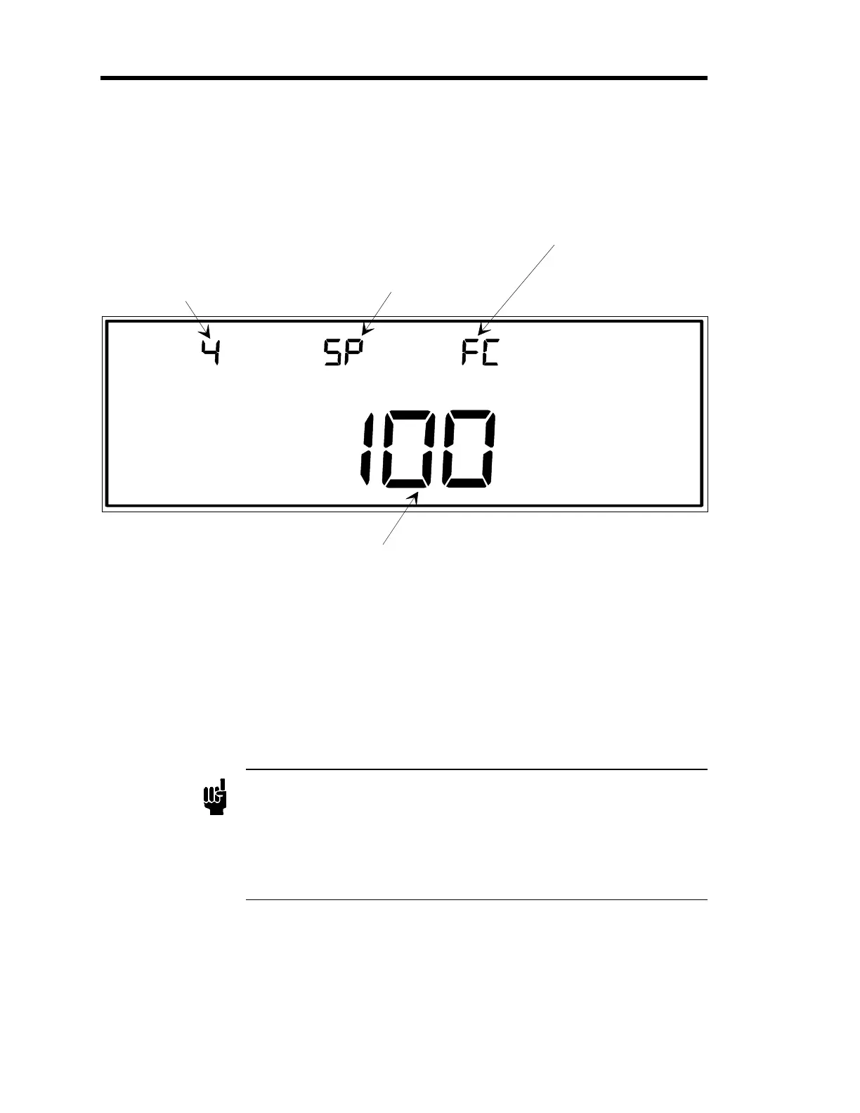
LEFT DISPLAY
CENTER DISPLAY RIGHT DISPLAY
MAIN DISPLAY
This is the ran
e of the mass flow controller (in sccm).
SETUP
SENSOR CAL
The number for the input
channel is entered here.
In this example, channel 4
is selected as the input
channel.
This displays the mode of
operation, SP for Set Point
(as here), to for Totalin
,
rA for Ratio. The mode of
operation is editable with
code 17x.
The FC indicates
Flow Controller.
Figure 60: Sensor Calibration for Mass Flow Controllers
An MFC is indicated by the code
FC
in the right display. The three modes of operation for an
MFC are
Set Point,
Totaling
and
Ratio
. The different modes are indicated by codes in the center
display:
SP
for the Set Point mode;
to
for the Totaling mode; and
rA
for the Ratio mode.
To change the mode of operation, refer to
Code 17x: How To Set Up the MFC,
page 241.
The only editable parameter in the MFC sensor calibration display is the range of the MFC.
Note
1. The range of the mass flow controller must be entered in sccm
(standard cubic centimeters
er minute). You cannot chan
e the units
to slm (standard liters per minute).
2. The mode of operation, displayed in the center display, cannot be
changed through this screen. Refer to
Code 17x: How To Set Up the
MFC,
page 241, to change the operating mode.
Artisan Technology Group - Quality Instrumentation ... Guaranteed | (888) 88-SOURCE | www.artisantg.com