How To Adjust Integral Cha
ter Six: O
eration in Tunin
Mode
168
How To Adjust Integral
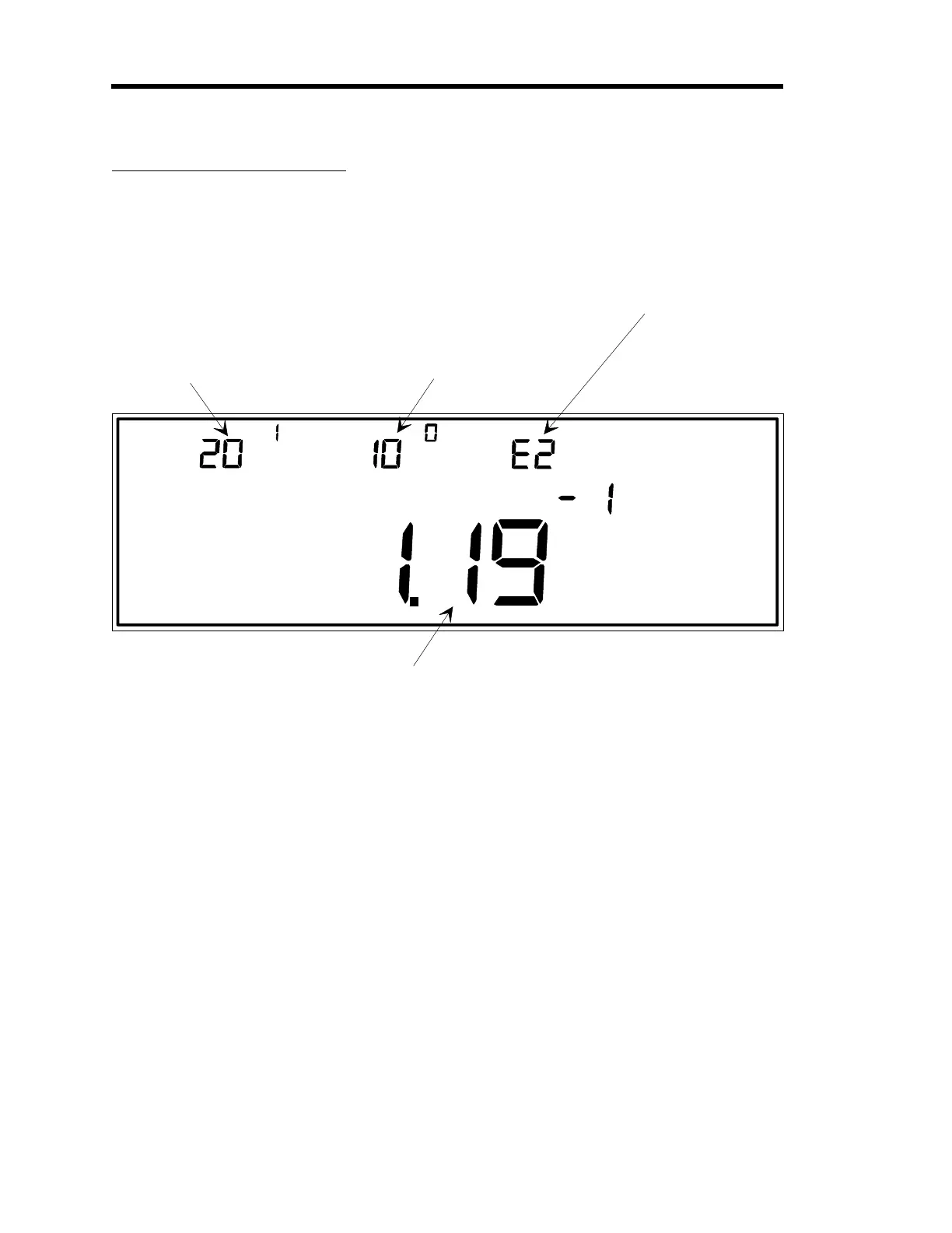
LEFT DISPLAY
CENTER DISPLAY RIGHT DISPLAY
This is the current valve
position expressed as a
percent of the valve
control si
nal output.
This example shows a
settin
of 20.1% of the
valve control si
nal
output.
The INTEGRAL parameter
selects the time constant for
PID calculations.
In this example, INTEGRAL
is the parameter which is
selected for editin
, and
is currently set at 10.0.
This indicates which of the
four possible recipes is
selected for editin
(in this
case, it is recipe 2).
MAIN DISPLAY
This is the pressure readin
from the
au
e on the control channel.
MANUAL
TORR
TUNING
INTEGRAL
Figure 48: Adjusting the Integral Value
The Integral parameter selects the time constant used for PID calculations.
1. Repeatedly press the [
DISPLAY MODE
] key until the 146 unit is in Tuning Mode.
The system responds by scrolling through modes.
2. Select the
INTEGRAL
parameter by scrolling through the parameters with the arrow
keys.
The system responds by displaying each of the Tuning parameters as they are scrolled
through.
3. Press the [
ENTER
] key.
The system responds by causing the center display to blink.
Artisan Technology Group - Quality Instrumentation ... Guaranteed | (888) 88-SOURCE | www.artisantg.com