Chapter Three: Overview Inside the T
e 146 Unit
77
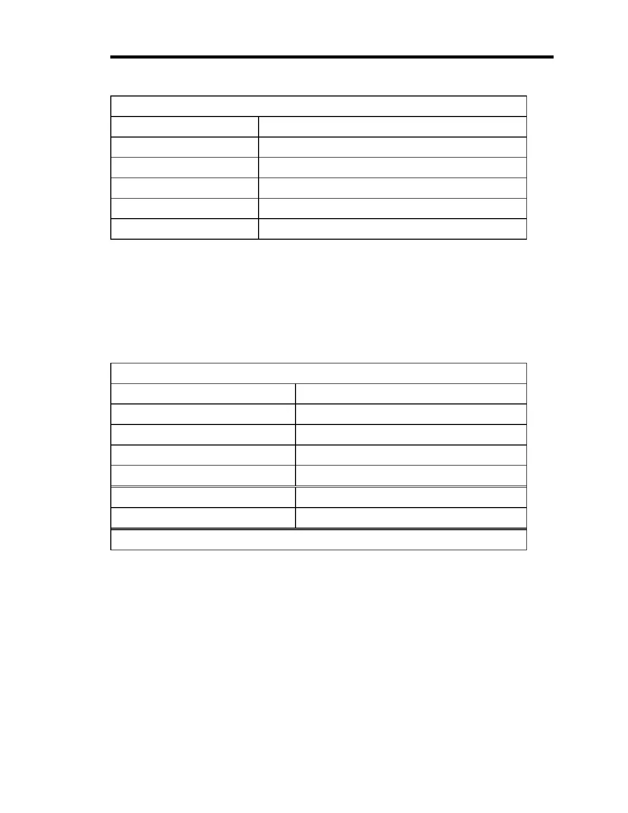
BCD Connector Pinout (Continued)
Pin Number Assignment
12 Inverse of Status
2, 14 External Digital Ground
13 Digital Ground (Reserve)
1 and shell Chassis Ground
15 Digital +5 Volts (Reserved)
Table 31: BCD Board Pinout
The RS-232 Connector
Located on the rear panel is the standard, 9-pin male Type “D” connector that is used for serial
communications. Table 32 lists the pin functions employed by this interface. The
RS-232
Communications
chapter describes the RS-232 protocol used in the 146 unit.
RS-232 Connector Pinout and Cables
Pin Number Assignment
2TXD
*
3RXD
*
5 Digital Ground
7CTS
*
Cable for AT
®
or compatible CB-146-2, CB-146S-2
Cable for XT
®
or compatible CB-146-4, CB-146S-4
*
TXD =Transmit Data, RXD =Receive Data, CTS =Clear To Send
Table 32: RS-232 Connector Pinout and Cables
Artisan Technology Group - Quality Instrumentation ... Guaranteed | (888) 88-SOURCE | www.artisantg.com