Chapter Nine: RS-232 Communications Command Messa
es
261
Calibration Messages
Depending upon the type of sensor, calibration may involve adjusting the zero, the span, or both
the zero and span.
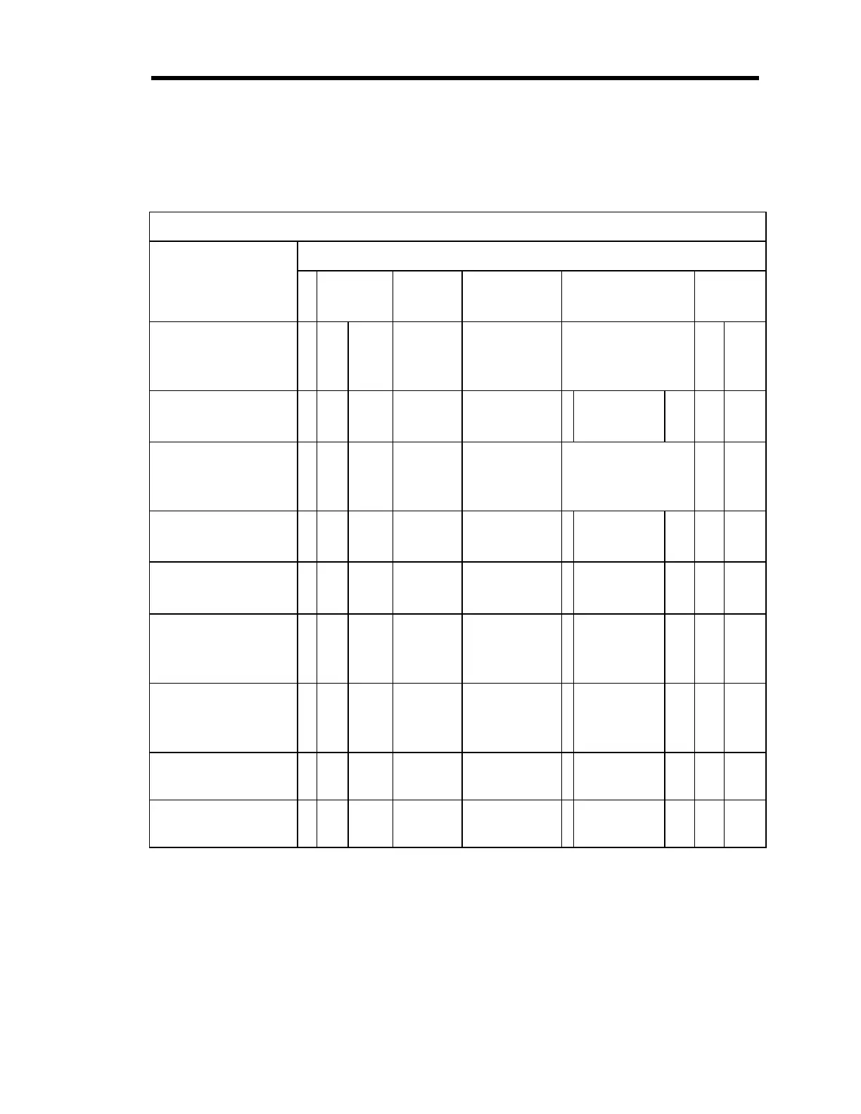
Calibration Messages
Message Description Message Format
@
command
category
command
number
Parameter Data
Optional
checksum
Zero Channel @ 0 5 1
1, 2, 3, or 4
(channel #)
or
S (set point)
CR
c1 c2
Define Lower Analog
Set Point Input
@0 5 2
Any character
:
Min. Voltage
in ASCII
CR
c1 c2
Span Channel @ 0 5 3
1, 2, 3, or 4
(channel #)
or
S (set point)
CR
c1 c2
Define Upper Analog
Set Point Input
@0 5 4
Any character
:
Max Voltage
in ASCII
CR
c1 c2
Span Channel with
reference
@0 5 5
1, 2, 3, or 4
(channel #)
: 1, 2, 3, or 4
(channel #)
CR
c1 c2
Zero On/Off @ 0 5 6
1, 2, 3, or 4
(channel #)
or
S (set point)
:ON = On
OFF = Off
CR
c1 c2
Span On/Off @ 0 5 7
1, 2, 3, or 4
(channel #)
or
S (set point)
:ON = On
OFF = Off
CR
c1 c2
Enable Auto Zero @ 0 5 8 1, 2, 3, or 4
(channel #)
: E = Enable
D = Disable
CR
c1 c2
Select Auto Zero
Reference Channel
@ 0 5 9 1, 2, 3, or 4
(channel #)
: 1, 2, 3, or 4 CR
c1 c2
Table 57: Calibration Messages
Artisan Technology Group - Quality Instrumentation ... Guaranteed | (888) 88-SOURCE | www.artisantg.com