Chapter Eight: Operation in Control Mode General Information
249
The Deviation Indicator
In Control Mode there is a deviation indicator which indicates the deviation of the system
pressure from set point. The deviation from set point is displayed approximately every one-third
second (this is how often the LCD screen is refreshed). The deviation indicator is enabled only if
the 146 unit is operating with the Auto feature turned on (refer to
How To Set the Valve to AUTO
Position, page 252).
There are ten deviation indicator segments on the front panel (refer to Figure 12, page 43). Five
segments represent pressure over set point and five represent pressure under set point. The 146
unit determines the segment(s) to illuminate according to the following formula:
Deviation =
P
sp
where: P = pressure
sp = set point
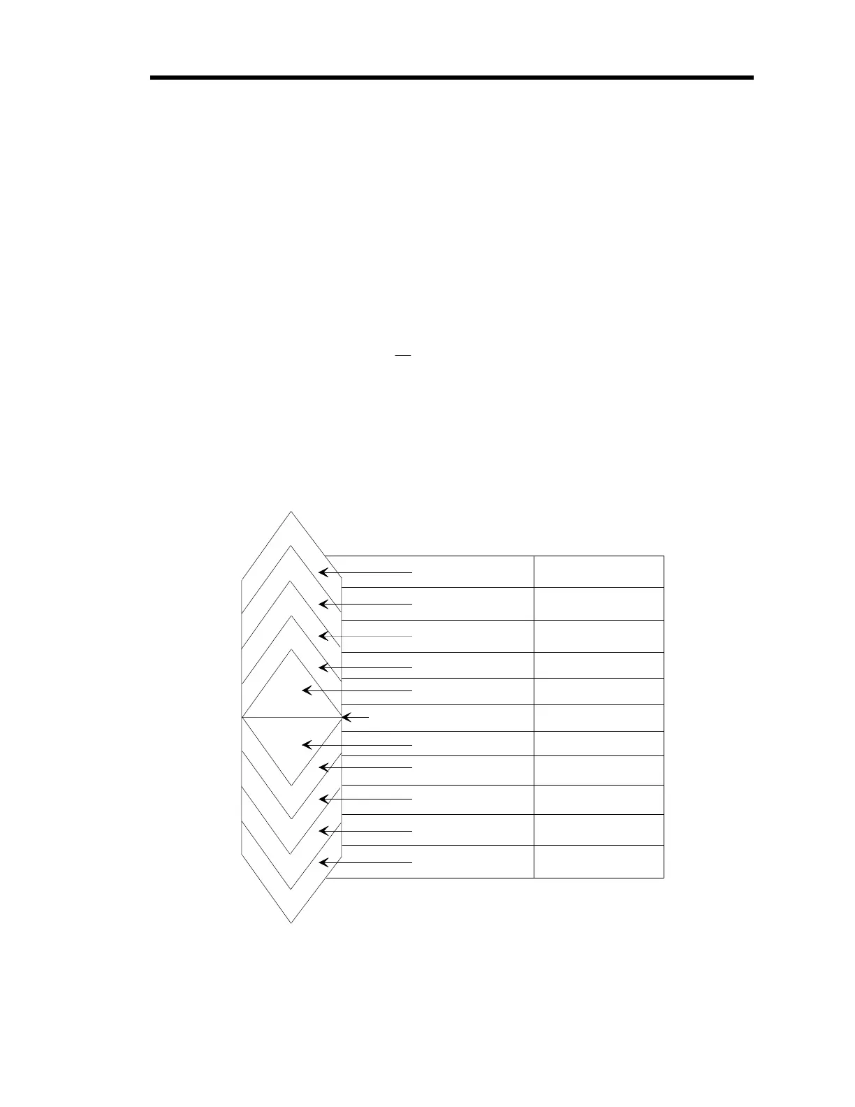
Each segment represents a different percent of deviation as shown in Figure 84.
Deviation Percent Error
Se
ments
1.2 to < 1.95
1.05 to < 1.2
1.01 to <1.05
1.002 to < 1.01
None = 0.998 to <1.002
0.99 to < 0.998
0.95 to < 0.99
0.80 to <0.95
0.05 to < 0.80
<0.05
> +95%
+20 to 95%
+5 to 20%
+1 to 5%
+0.2 to 1%
0.2%
-0.2 to 1%
-1 to -5%
-5 to -20%
-20 to -95%
> -95%
±
1.95
≥
Figure 84: Deviation Indicator
Artisan Technology Group - Quality Instrumentation ... Guaranteed | (888) 88-SOURCE | www.artisantg.com