8 Operation
Maschinenfabrik Reinhausen GmbH 2020184 3587317/21 ENTAPCON
®
▪ Desired load stress type
▪ Parallel operation error delay time
Note that the parameters "Error if no communication" and "Behavior if no
communication" have no function in the circulating reactive current mini-
mization without CAN communication parallel operation method.
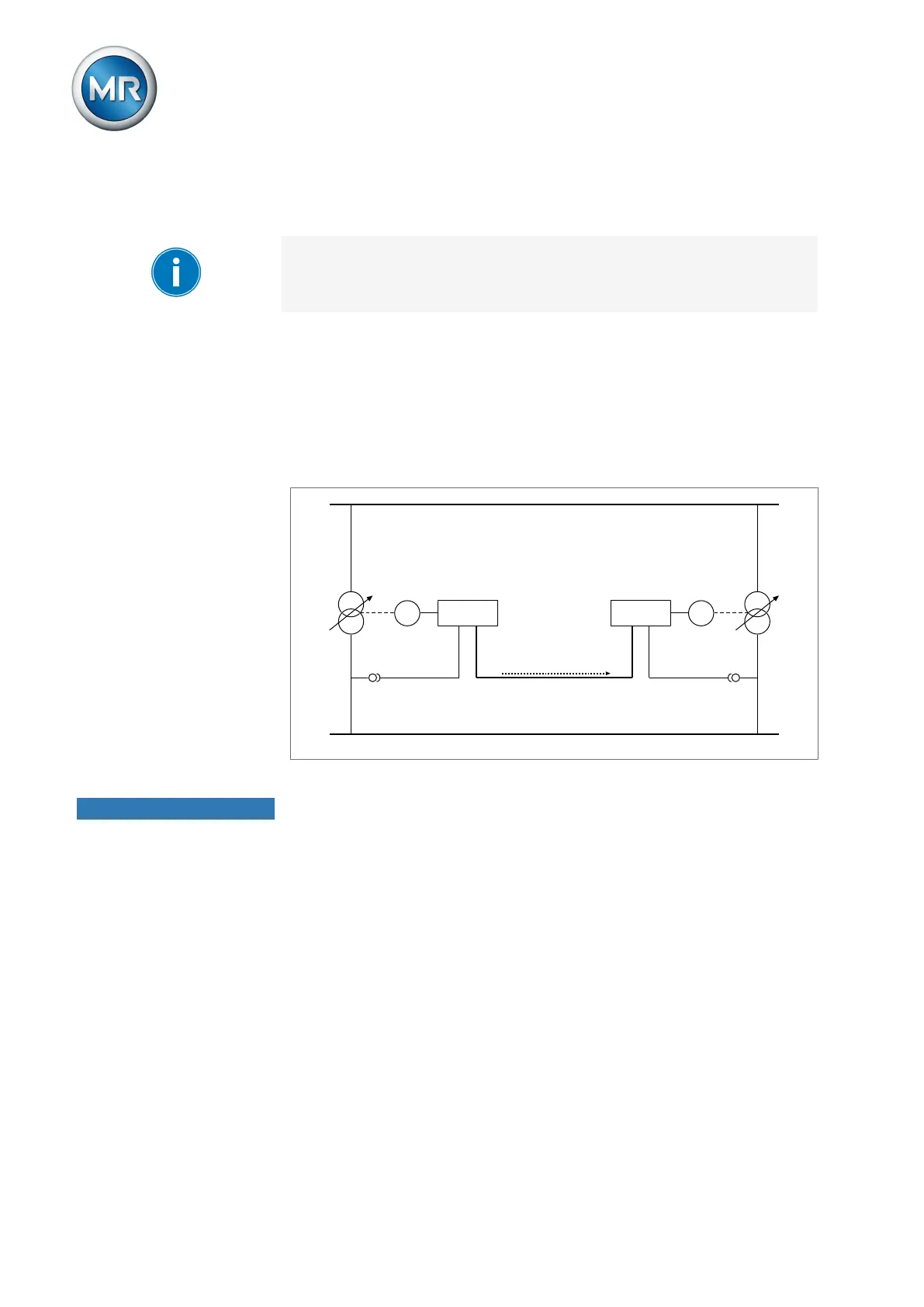
8.18.1.4 Tap stagger (optional)
The tap stagger parallel operation method is used to generate a defined cir-
culating reactive current in two transformers running in parallel in order to
compensate for the reactive power in the grid. In this case, one voltage regu-
lator works as the master and one voltage regulator as the follower. The
master handles voltage regulation and transmits the desired tap position to
the follower over the CAN bus.
Master Follower
Tap position
CAN bus
M AVR MAVR
T1 T2
Figure127: Tap stagger
NOTICE
Damage to the transformers
An inadmissibly high circulating reactive current can lead to the transform-
ers being damaged.
► Ensure that the circulating reactive current generated through the tap
stagger parallel operation method does not exceed the performance lim-
its of the transformers.
Function To generate a defined circulating reactive current, you must select the de-
sired tap stagger level. Starting from the same tap position, the master and
follower then switch in opposing directions (e.g. tap stagger level = 2: master
+1, follower -1). The magnitude of the circulating reactive current depends
on how large the tap position difference is between the master and follower.
The on-load tap-changers switch in opposing directions based on the setting
of the selected parameter until the desired tap stagger level is reached.