4 Product description
Maschinenfabrik Reinhausen GmbH 2020 353587317/21 EN TAPCON
®
4.6.4 Front interface
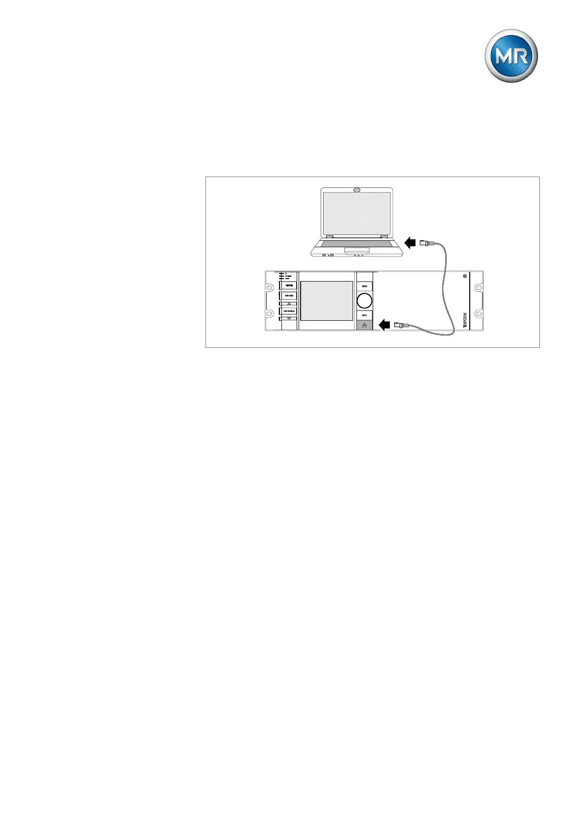
The parameters for the device can be set using a PC. The RJ45 Ethernet in-
terface on the front panel is provided for this purpose. To establish a con-
nection with the device, refer to the Visualization section.
Figure14: Device connection to a PC
4.6.5 Assemblies
Depending on configuration, the device may have various assemblies which
perform the functions required. The functions of the assemblies are de-
scribed in the following sections. You will find more information about the as-
semblies in the Technical data [►Section 15, Page 312] section.
4.6.5.1 Power supply
The OT1205 assembly contains the power supply unit for powering the de-
vice. Depending on configuration, the device is equipped with one of the fol-
lowing power supply unit variants:
▪ Multi-voltage mains unit 85...265 VAC/VDC
▪ DC voltage power supply unit 20...70 VDC
4.6.5.2 CPU (central processing unit) I
The CPU I assembly is the central processing unit for the device. It contains
the following interfaces:
▪ Internal system interface RS232 (COM1)
▪ Serial interface RS232/485 (COM2)
▪ 3x Ethernet (ETH1, ETH 2.1, ETH 2.2)
▪ USB (USB 2.0)
▪ 2x CAN bus (CAN 1, CAN 2)