7 Commissioning
Maschinenfabrik Reinhausen GmbH 2020 753587317/21 EN TAPCON
®
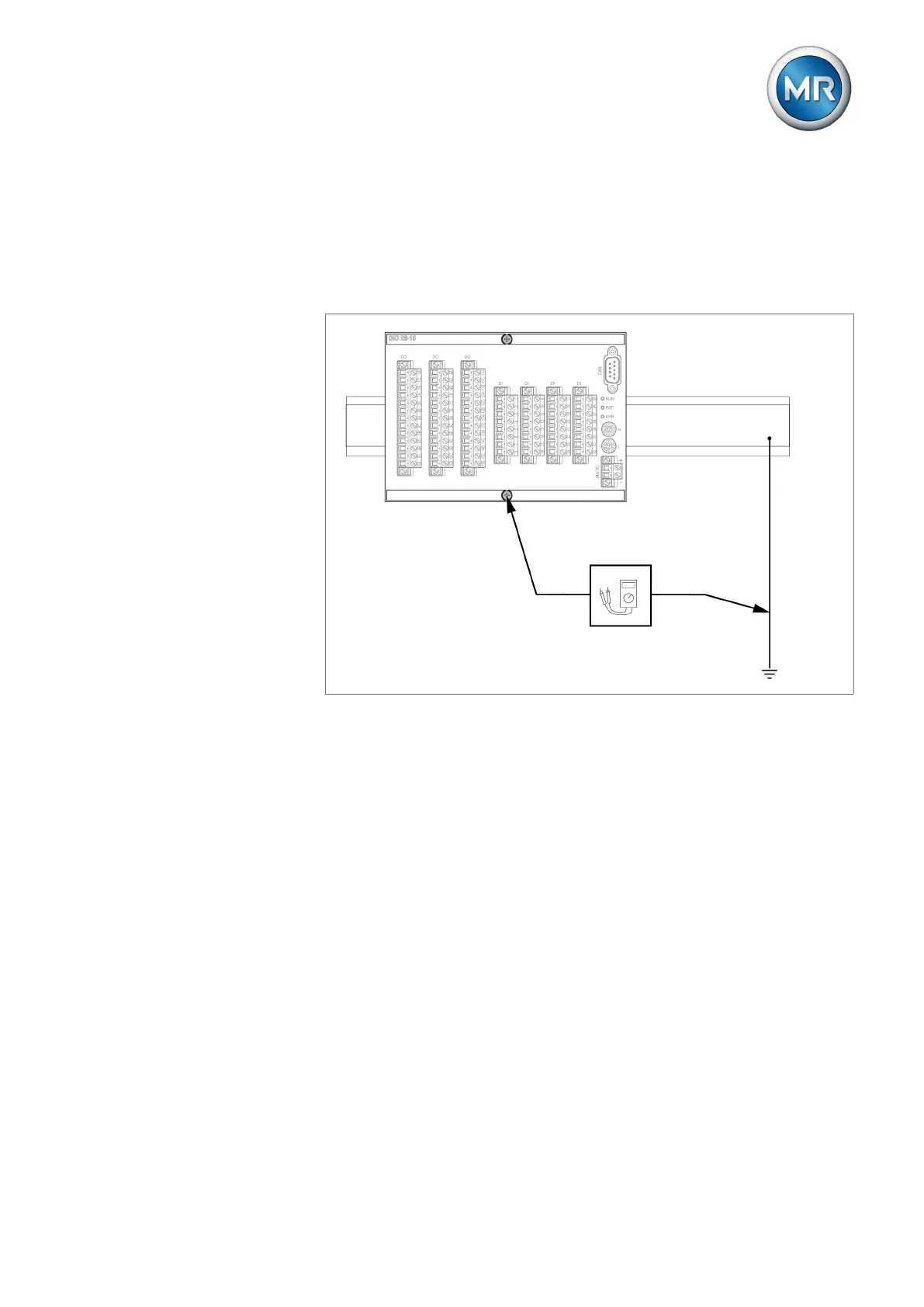
Proceed as follows to carry out the ground test:
1. Feed the test current at the fixing screw of assembly DIO 28-15 or DIO
42-20 using a constant current source and measure the voltage between
the measurement point and the protective conductor.
ð The measured voltage must remain less than 10 V over a duration of 1
minute.
Figure63: Perform a ground test on the DIO assembly (sample representation of the DIO 28-15
assembly).
2. Feed the test current at the grounding terminal of the G1 PULS DIMEN-
SION QS3.241 assembly using a constant current source and measure
the voltage between the measurement point and the protective conductor.
ð The measured voltage must remain less than 10 V over a duration of 1
minute.