XPS Unified Programmer’s Manual
6.5.3 Status, Error, and High Nibble P2 Interface Register
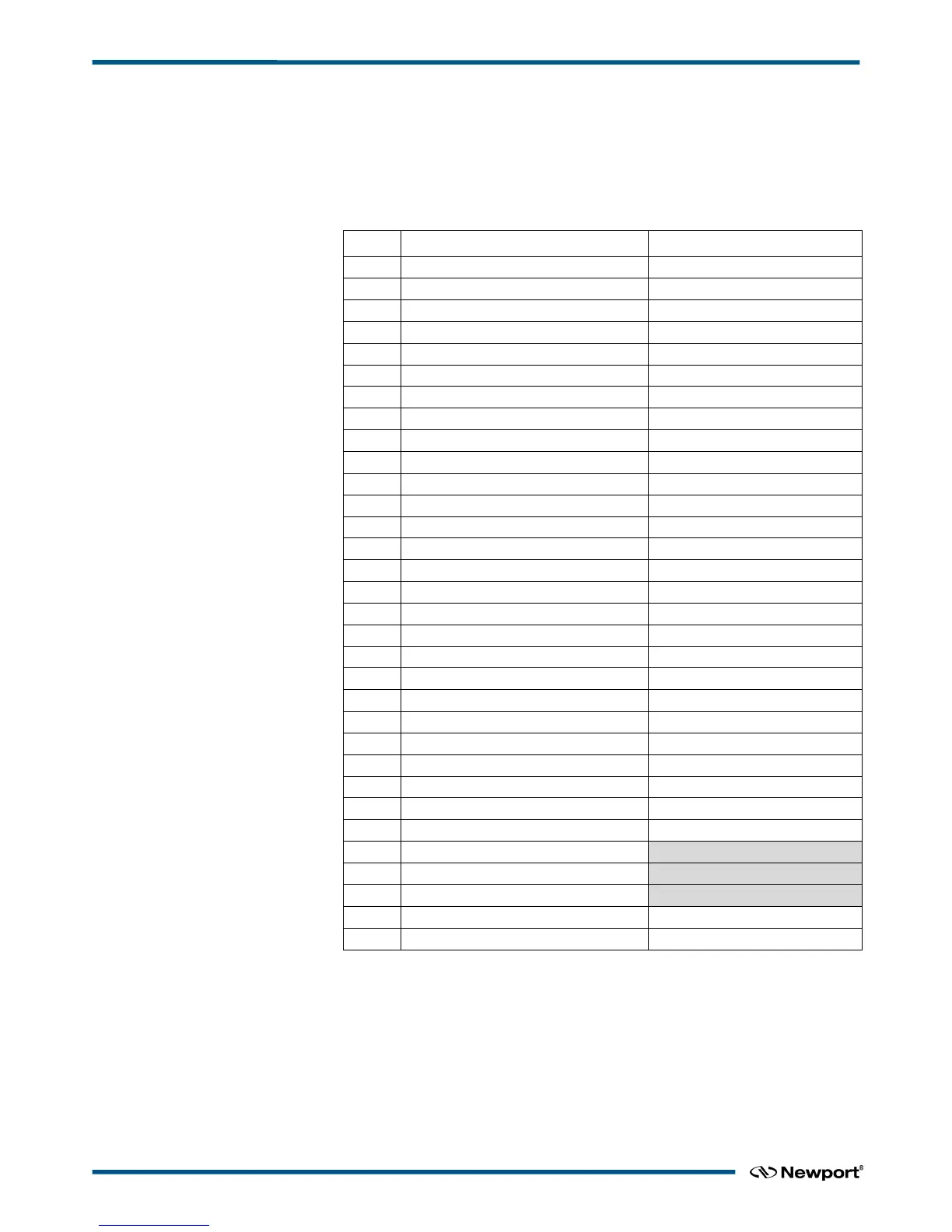
This register contains the status bits, error bits, and the 4 high order position data bits.
The table below lists the bit positions of these signals in the register. See “Error
Detection and Status Reporting” section for more information. The bits that correspond
to fatal errors are indicated by “(F)”.
Table 3-4 Status, Error, and High Nibble P2 Interface Register Bit Positions
XPS group state after detection
Measurement Signal Present
(F) Reference Signal Missing
(F) Measure Signal Missing
(F) Measure Signal Dropout
(F) Measure Signal Glitch
(F) 36 bit Position Overflow
The high nibble bits are latched at the same time as the P2 Position register, and should
be read after the position is read. The error bits (21-31) have the same meaning as the
corresponding errors in the VME Error Status register (bits 0-10). The P2 Error register
is set and reset separately from the VME Error Status register.
The status bits (16-20) have the same meaning as the corresponding status bits in the
VME Status Register (bits 0-4). The User Bit shows the state of the User P2 bit in VME
Control Register 1.
EDH0373En1023 — 01/18 38

 Loading...


