XPS Unified Programmer’s Manual
6.5.5 PEG Control Register
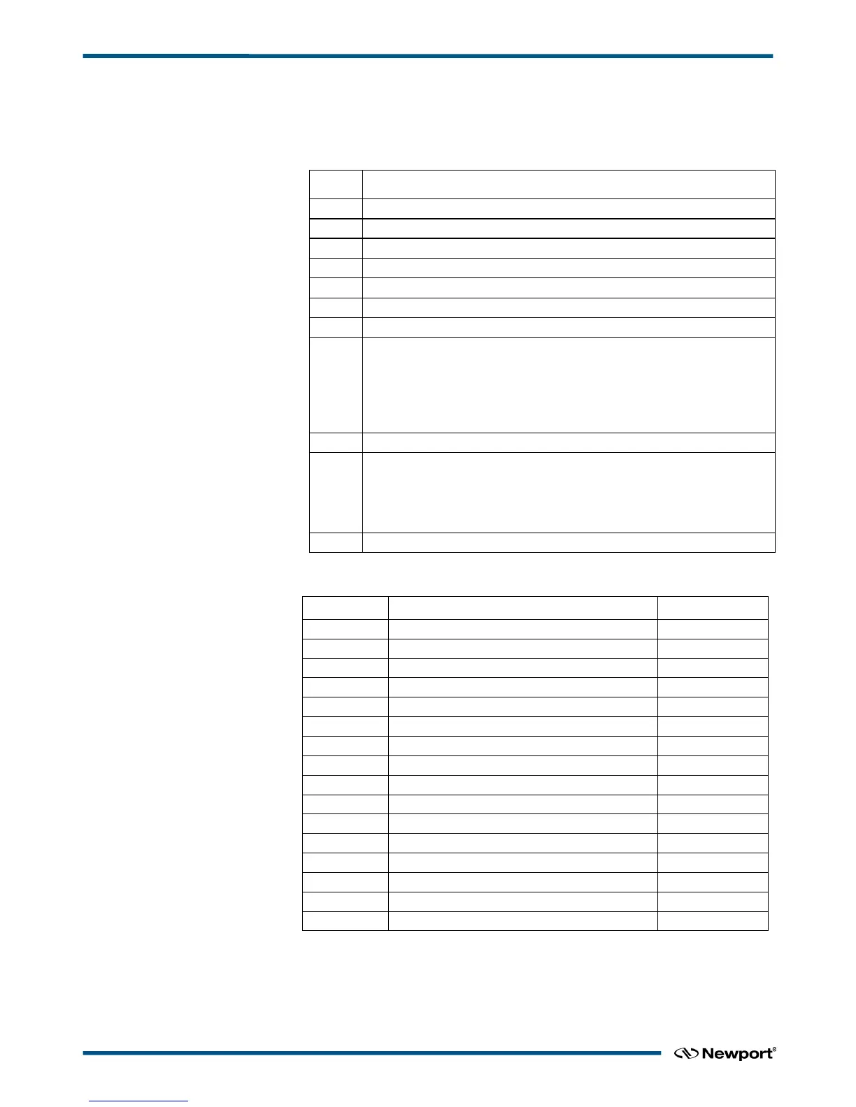
The bit assignments of the PEG Control register are listed below. The PEG Enable
Control and PEG Disable Control fields control the overall operation of the PEG
subsystem.
Bit Description
PEG Pulse Width (00 = 25 ns, 01 = 50 ns, 10 = 75 ns, 11 = 100 ns)
PEG Axis Select (0 = axis 1, 1 = axis 2)
PEG Output Polarity (0 = Low pulse, 1 = High pulse)
0 = NO_EXIT = Don’t disable
1 = P1_EXIT = Disable at P1 exit
2 = P2_EXIT = Disable at P2 exit
3 = ANY_EXIT = Disable at P1 or P2 exit
4 = IMM_EXIT = Disable immediately
PEG P2 Delta (0 = Delta 1, 1 = Delta 2)
0 = NO_ENT = Don’t enable
1 = P1_ENT = Enable at P1 entry
2 = P2_ENT = Enable at P2 entry
3 = ANY_ENT = Enable at P1 or P2 entry
6.5.6 ZYGO Axis Error Status List
Reference signal is missing
The axis error status register is read via Ethernet. A XPS controller error is generates
when one or several bits of Error mask are ON. In this case, the group goes to
NOTINIT state.
EDH0373En1023 — 01/18 40

 Loading...


