Scrub System 310Service Manual – CS7000
4.
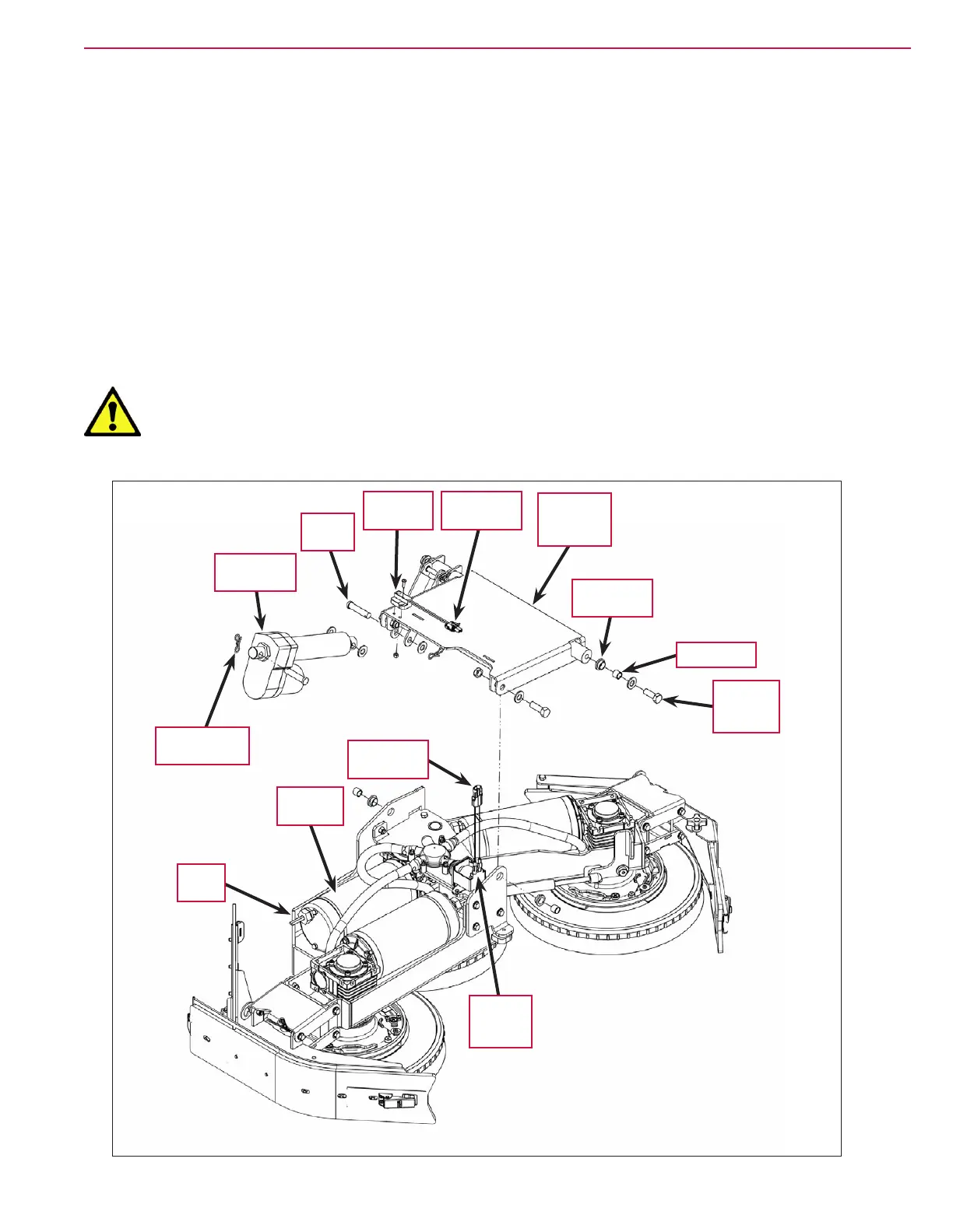
5. Disconnect the Electrical Connectors to the three Scrub Motors, to the Proximity Sensor on the Deck Lift Arm
Assembly
and to the Solution Solenoid Valve. Jog the Scrub Deck up or down as necessary to access the
Electrical Connectors. Note that you may need to cut wire ties to access the Electrical Connectors.
6. Extend the scrub deck downward in the Service Test mode to minimize the weight on the M12-1.75 x
35mm Screws
supporting the Deck Lift Arm Assembly and Scrub Deck.
7. Remove the two M12-1.75x 35mm Screws, washers, Bushings and Flange Bearings holding the Deck Lift Arm
Assembly
and attached Scrub Deck to the machine frame.
8. Remove the Bow-tie Cotter Pin, washers and Clevis Pin holding the Scrub Deck Actuator to the Deck Lift Arm
Assembly
.
9. Jack the machine up as necessary to get enough clearance to remove the Scrub Deck, then support the
machine with jack stands.
Warning! Never work under a machine without safety stands or blocks to support the machine.
When jacking the machine, do so at the designated Tie Down/Jacking Locations.
10. Slide the Scrub Deck and attached Deck Lift Arm Assembly out from under the machine.
Flange
Bearing (2)
Bushing (2)
Scrub Deck
Actuator
M12-1.75
x 35mm
Screw (2)
Clevis
Pin (2)
Solution
Solenoid
Valve
Proximity
Sensor
Scrub
Deck
Electrical
Connector
Deck
Lift Arm
Assembly
Electrical
Connector
Bow-tie Cotter
Pin (2)
Scrub
Motor (3)

 Loading...


