83
F3SG-R
User’s Manual
Chapter2 Floating Blanking
System Operation and Functions
E
Detection Capability
Detection capability for F3SG-RA differs based on the number of floating beams as shown below.
F3SG-R LED Indicator status
When floating blanking is being enabled, the Blanking indicator turns on.
Refer to 2-1. Combination of Functions for more information on the use in conjunction with other functions.
2-15-2. Factory Default Setting
The factory default setting is the Floating Blanking Disabled.
2-15-3. Setting with DIP Switch
Configuring the blanking setting of the DIP switch as Floating Blanking Enabled enables the floating
blanking function.
The floating blanking monitoring function is configured as lockout.
Make sure the Position 8 of the DIP Switch is set to Configuration Tool Enabled to activate the settings by the
Configuration Tool.
Refer to Chapter 3 Setting with DIP Switch for more information on setting this function by the DIP Switch.
Model Number of beams configured Detection capability
Number of blocked beams to turn safety
outputs OFF
F3SG-4RA-14
- 14 mm 1 beam
1 beam 24 mm 2 beams
2 beams 34 mm 3 beams
3 beams 44 mm 4 beams
4 beams 54 mm 5 beams
n beams 14+(10×n) mm (n+1) beams
F3SG-4RA-30
- 30 mm 1 beam
1 beam 50 mm 2 beams
2 beams 70 mm 3 beams
3 beams 90 mm 4 beams
4 beams 110 mm 5 beams
n beams 30+(20×n) mm (n+1) beams
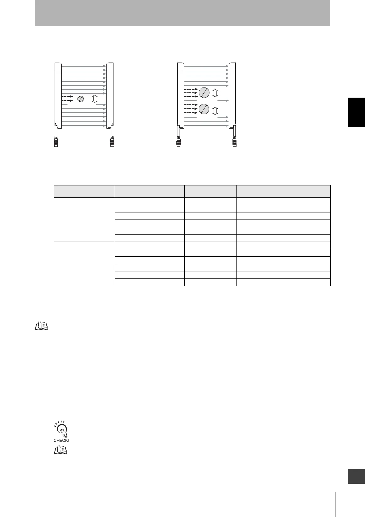
Lockout
More than one zone is blocked
Fig. 3 Fig. 4
Safety output OFF
2 or fewer are blocked
30-mm dia.
30-mm dia.
14-mm dia. max.

 Loading...


