8
Chapter1 LED Indicators
F3SG-R
User’s Manual
Overview and Specifications
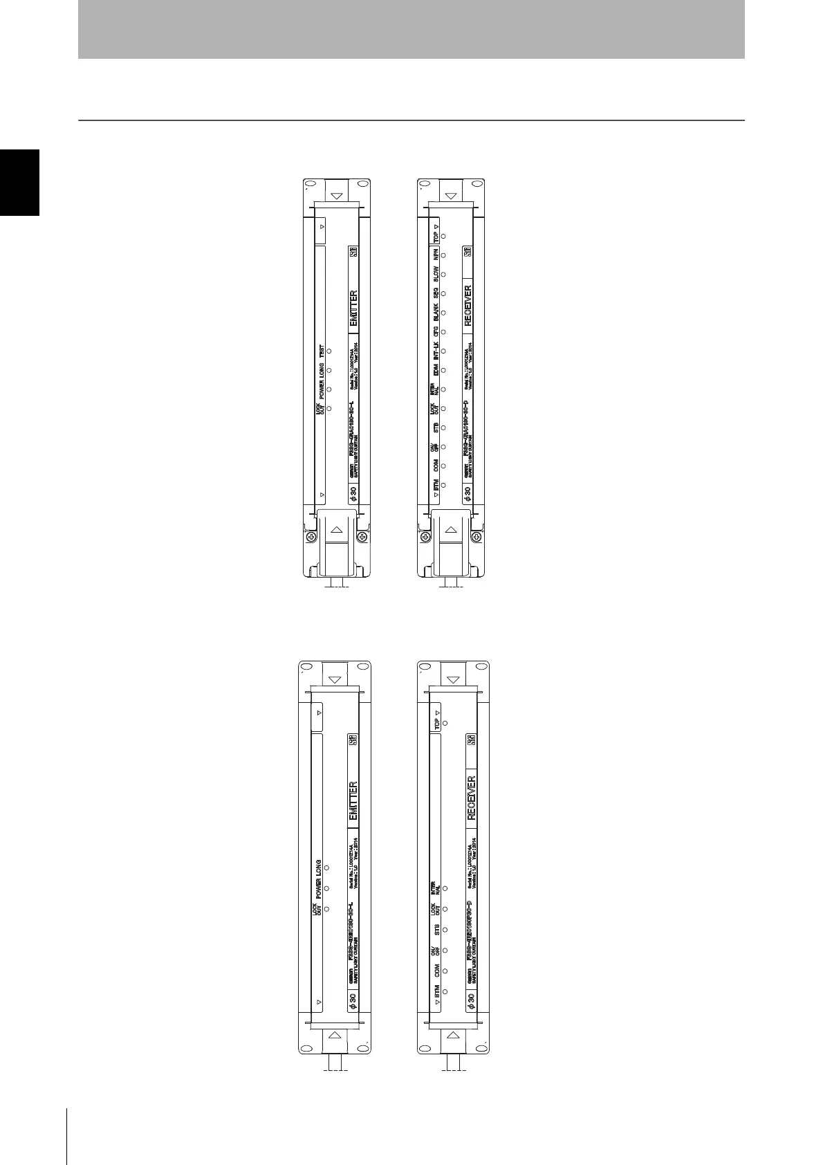
1-4. LED Indicators
F3SG-RA Series
F3SG-RE Series
<Emitter> <Receiver>
1. Top-beam-state indicator (Blue)
2. PNP/NPN mode indicator (Green)
3. Response time indicator (Green)
4. Sequence error indicator (Yellow)
1. Test indicator (Green)
2.
Operating range indicator (Green)
3. Power indicator (Green)
4. Lockout indicator (Red)
5. Blanking indicator (Green)
6. Configuration indicator (Green)
7. Interlock indicator (Yellow)
8.
External device monitoring indicator (Green)
9. Internal error indicator (Red)
10. Lockout indicator (Red)
11. Stable-state indicator (Green)
12. ON/OFF indicator (Green/Red)
13. Communication indicator (Green)
14. Bottom-beam-state indicator (Blue)
1. Top-beam-state indicator (Blue)
2.
Operating range indicator (Green)
3. Power indicator (Green)
4. Lockout indicator (Red)
9. Internal error indicator (Red)
10. Lockout indicator (Red)
11. Stable-state indicator (Green)
12. ON/OFF indicator (Green/Red)
13. Communication indicator (Green)
14. Bottom-beam-state indicator (Blue)
<Emitter> <Receiver>

 Loading...


