25
F3SG-R
User’s Manual
Chapter2 Optical Synchronization
System Operation and Functions
E
2-3. Optical Synchronization
2-3-1. Overview
Synchronization is required between an emitter and a receiver for normal operation of F3SG-R.
F3SG-R uses a specific beam for Synchronization. The beam is hereinafter called synchronization
beam.
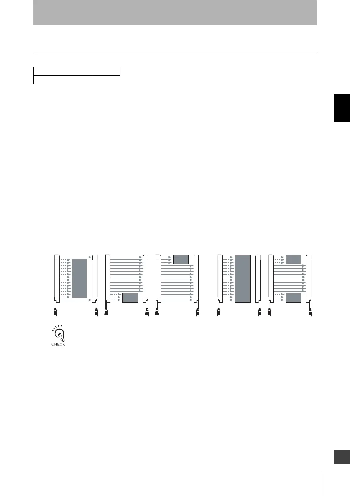
Depending on sensor configuration, the synchronization beam is either of the followings:
• One segment system: End beams (Top or Bottom beam)
• Cascaded system* : End beams (Top or Bottom beam) of the primary sensor
* The F3SG-RE cannot be used in cascade connection.
For an emitter and a receiver to synchronize, at least one synchronization beam must be unblocked.
The synchronization process is performed when:
(1) The power is turned on for an emitter and a receiver
(2) All beams of the primary sensor are blocked and then unblocked
(3) Synchronization is lost due to an error such as noise and ambient light
The sensor can maintain the synchronization in other cases than those described above and it is not necessary to keep
the synchronization beam unblocked all the time.
Response time of “OFF (Synchronized) → ON” and “OFF (Not synchronized) → ON”
Response time of “OFF (Synchronized) → ON” is the response time from when the F3SG-R is in the
OFF state and the emitter and receiver are synchronized to when the F3SG-R is turned to the ON
state.
Response time of “OFF (Not synchronized) → ON” is the response time from when the F3SG-R is in
the OFF state and the emitter and receiver are not synchronized to when the F3SG-R is turned to the
ON state. This response time is longer since the F3SG-R evaluates if it is blocked or unblocked, after
the synchronization is established.
F3SG-RA Series X
F3SG-RE Series X
Upper Upper
Lower Lower
Upper Upper
Lower Lower
Upper Upper
Lower Lower
Upper Upper
Lower Lower
Conditions to establish synchronization
Conditions to fail synchronization
Upper Uppe
Lower Lower

 Loading...


