199
F3SG-R
User’s Manual
Chapter5 Wiring Examples (F3SG-RE Series)
Input/Output Circuit and Applications
E
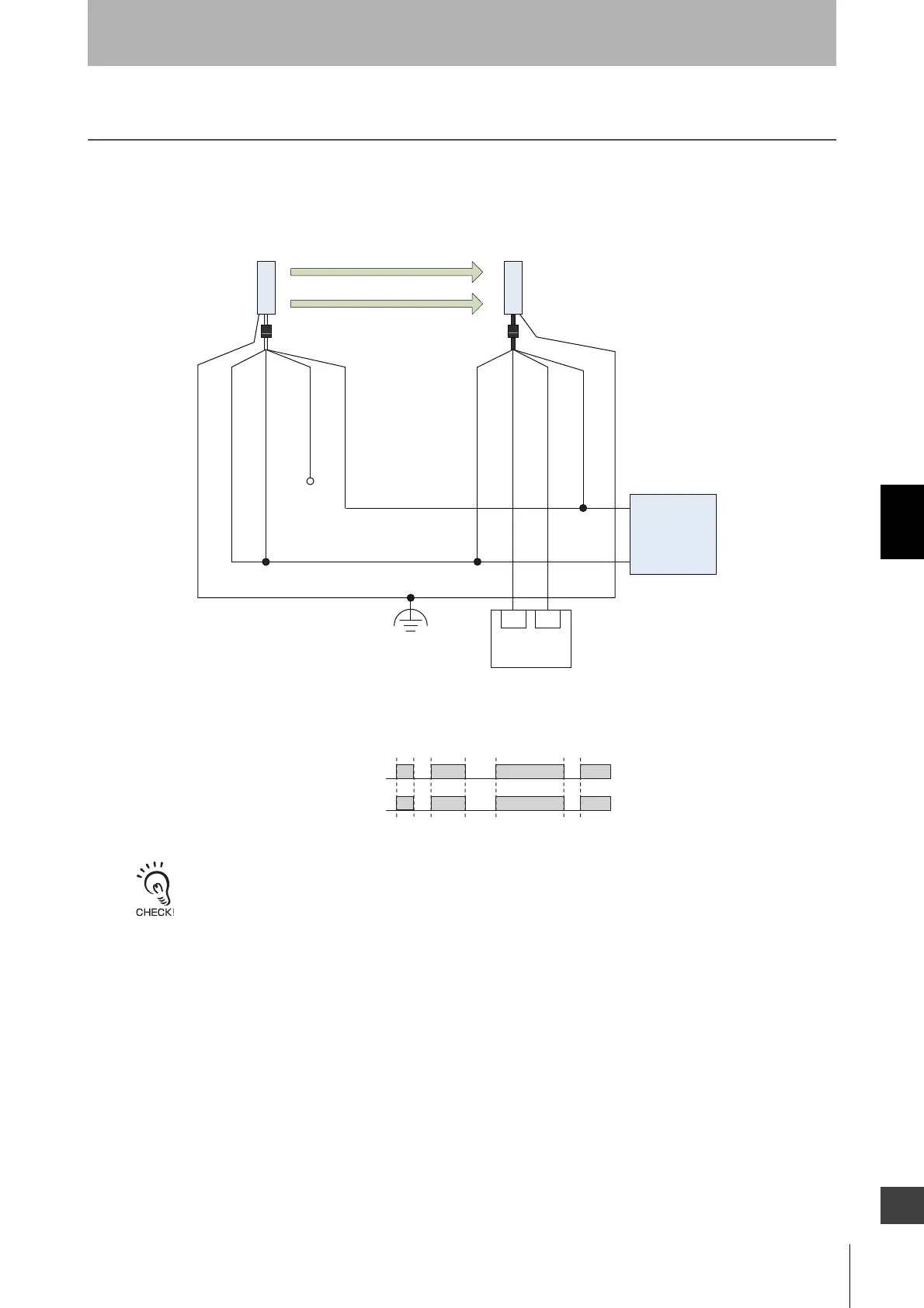
5-3. Wiring Examples (F3SG-RE Series)
Examples of a motor control system using the F3SG-RE are shown below. This chapter shows
examples equivalent to ISO 13849-1 (PL e/Category 4).
5-3-1. Short Mode
The wiring examples in later pages do not indicate functional earth. To use functional earth, wire an earth cable
according to the example above. Refer to 4-5-5. Functional Earth Connection for more information.
+24 V
0 V
OSSD1 : Black
OSSD2 : White
Operating Range
Select Input : White
24 VDC : Brown
Not used : Black
24 VDC : Brown
0 V : Blue
Receiver
Emitter
0 V : Blue
DC
Power
Supply
Safety
Controller *1 *2
IN1
IN2
Unblocked
Blocked
OSSD
Functional Earth
Beam state
*1. Refer to 5-4. Connectable Safety Control Units for more information.
*2. The safety controller and the F3SG-R must share the power supply or
be connected to the common terminal of the power supply.

 Loading...


