154
Chapter4 Mounting
F3SG-R
User’s Manual
Wiring/Installation
4-4-3. Mounting Procedure
Before mounting (in case of F3SG-RA)
When it is required to configure functions with DIP Switch, do so before installing the F3SG-RA in your
site, according to the procedure described in 3-2. DIP Switch.
The mounting procedure is the same between F3SG-RA and F3SG-RE series.
4-4-3-1. Mounting with Standard Fixed Brackets (F39-LGF)
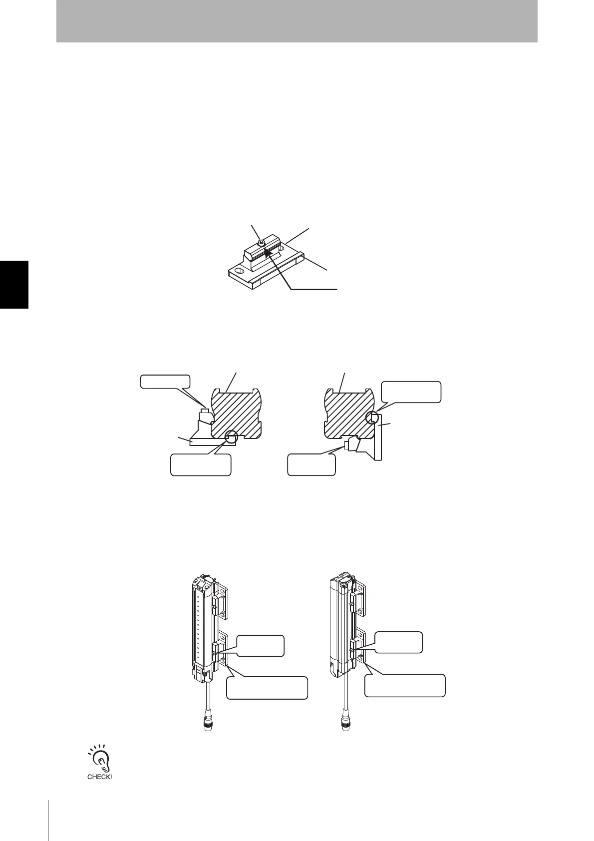
1. Loosen the hexagon socket head cap screws (M3 x 15). (Fig.1)
2. Slide the hook of the Fixed Bracket (1) in the groove of the F3SG-R housing. Lightly tighten the
hexagon socket head cap screw (M3 x 15). (Fig. 2)
3. Adjust the Standard Fixed Bracket to the mounting position of the wall surface. Securely tighten the
hexagon socket head cap screw (M3 x 15) to fix the Standard Fixed Bracket to the housing of the
F3SG-R. The recommended torque to tighten the hexagon socket head cap screw (M3 x 15) is 2.0
N•m. (Fig. 3)
Tightening screws with a torque that considerably exceeds the recommended torque may cause failure.
hook
Fig. 1
Loosen this
Hexagon socket head
cap screw (M3 x 15)
Fixed Bracket
<Backside mounting> <Side mounting>
Optical surface
of F3SG-R
Optical surface
of F3SG-R
Loosen this
Fixed Bracket
Fixed Bracket
Slide the hook
in the groove
Lightly
tighten this
Fig. 2
Slide the hook
in the groove
<Backside mounting> <Side mounting>
Securely
tighten this
Adjust the bracket
to mounting position
Securely
tighten this
Adjust the bracket
to mounting position
Fig. 3

 Loading...


