194
Chapter5 Wiring Examples(F3SG-RA Series)
F3SG-R
User’s Manual
Input/Output Circuit and Applications
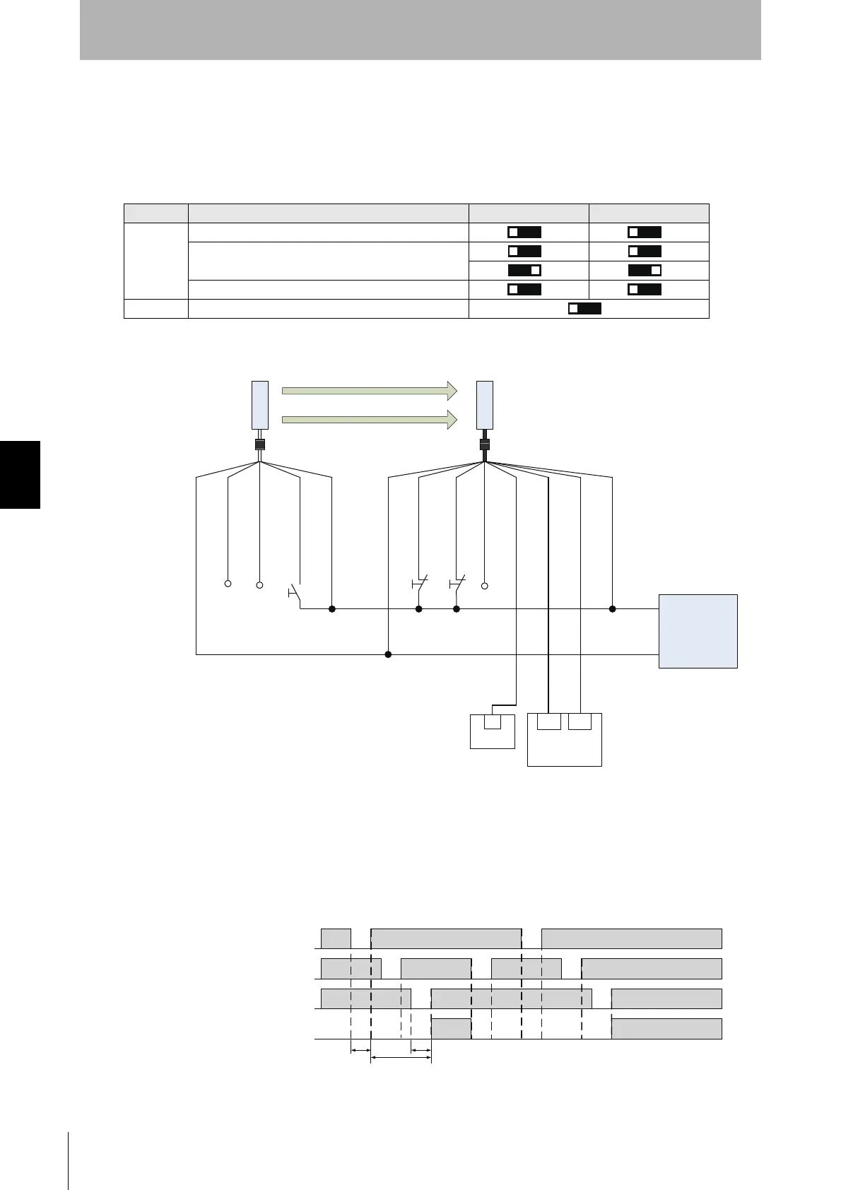
5-2-11. Pre-Resest Mode using PNP Output
The following is the example of External Device Monitoring disabled, Pre-Reset mode, PNP output and
External Test in 24 V Active.
[DIP Switch settings] *4
: Indicates a switch position.
Configure functions with the DIP Switches before wiring.
[Wiring Example]
Function DIP-SW1 DIP-SW2
Receiver
EDM Disabled (factory default setting)
Pre-Reset
PNP (factory default setting)
Emitter External Test: 24 V Active (factory default setting)
㻞㻻㻺
㻟㻻㻺 㻟㻻㻺
㻠㻻㻺 㻠㻻㻺
㻣㻻㻺
OSSD1 : Black
OSSD2 : White
24 VDC : Brown
Not used : Yellow
TEST : Black
Not used : White
24 VDC : Brown
0 VDC : Blue
Receiver
Emitter
0 VDC : Blue
AUX : Red
Not used : Pink
PRE-RESET : Gray
RESET : Yellow
S1: Test Switch (Connect the line to 0 V if this switch is
not required)
S2: Lockout/Interlock Reset Switch
S3: Pre-Reset Switch
PLC: Programmable controller
(Used for monitoring only. NOT related to safety system.)
S2 S3
F39-JGA-L F39-JGA-D
S1
Power Supply
+24 VDC
0 VDC
Safety
Controller *1 *2
IN1 IN2
PLC *3
IN
Pre-Reset Switch (S3)
Beam state
Reset Switch (S2)
OSSD
Unblocked
Blocked
T1: Push time: must be T1 >= 300ms
T2: Pre-reset limit time between Pre-reset and Reset: must be T2 <= 60s
T3: Push time: must be T3 >= 300ms
T1
T2
T3
*1. Refer to 5-4. Connectable Safety Control Units for
more information.
*2. The safety controller and the F3SG-R must share the
power supply or be connected to the common terminal
of the power supply.
*3. When connecting to the PLC, the output mode must
be changed with the Configuration Tool.
*4. The functions are configurable with DIP Switch. Refer
to Chapter 3 Setting with DIP Switch for more
information on setting the functions by the DIP Switch.

 Loading...


