11
F3SG-R
User’s Manual
Chapter1 Ratings/Specifications
Overview and Specifications
E
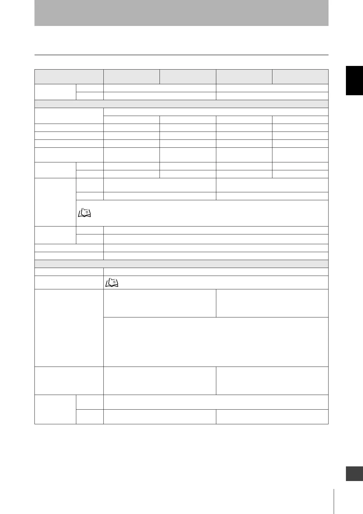
1-5. Ratings/Specifications
The in the model names indicate the protective heights in millimeters.
F3SG-4RA-14
F3SG-2RA-14
F3SG-4RA-30
F3SG-2RA-30
F3SG-4RE14
F3SG-2RE14
F3SG-4RE30
F3SG-2RE30
Type of ESPE
(IEC 61496-1)
Type 4 F3SG-4RA-14/-30 F3SG-4RE14/30
Type 2 F3SG-2RA-14/-30 F3SG-2RE14/30
Performance
Object Resolution
(Detection Capability)
Opaque objects
14-mm dia. 30-mm dia. 14-mm dia. 30-mm dia.
Beam Gap 10 mm 20 mm 10 mm 20 mm
Number of Beams 15 to 207 8 to 124 15 to 207 8 to 124
Lens Size 5.2 × 3.4 (W × H) mm 7-mm dia. 5.2 × 3.4 (W × H) mm 7-mm dia.
Protective Height 160 to 2080 mm (6.3 to
81.9 inch)
190 to 2510 mm (7.3 to
98.7 inch)
160 to 2080 mm (6.3 to
81.9 inch)
190 to 2510 mm (7.3 to
98.7 inch)
Operating Range
Long 0.3 to 10.0 m (1 to 32 ft.) 0.3 to 20.0 m (1 to 65 ft.) 0.3 to 10.0 m (1 to 32 ft.) 0.3 to 20.0 m (1 to 65 ft.)
Short 0.3 to 3.0 m (1 to 10 ft.) 0.3 to 7.0 m (1 to 23 ft.) 0.3 to 3.0 m (1 to 10 ft.) 0.3 to 7.0 m (1 to 23 ft.)
Response Time
ON to OFF
Normal mode: 8 to 18 ms *1
Slow mode: 16 to 36 ms *1 *2
5 to 15 ms
OFF to ON 40 to 90 ms *1 25 to 75 ms
*1. Response time when used in one segment system or in cascaded connection.
Refer to 1-6. List of Models for more information.
*2. Selectable by Configuration Tool.
Effective Aperture
Angle (EAA) (IEC
61496-2)
Type 4 ±2.5° max., emitter and receiver at operating range of 3 m or greater
Type 2
±5.0° max., emitter and receiver at operating range of 3 m or greater
Light Source Infrared LEDs, Wavelength: 870 nm
Startup Waiting Time 2 s max.
Electrical
Power Supply Voltage (Vs) SELV/PELV 24 VDC±20% (ripple p-p 10% max.)
Current Consumption
Refer to 1-6. List of Models
Safety Outputs (OSSD)
Two PNP or NPN transistor outputs (PNP or NPN
is selectable by DIP Switch.)
F3SG-REP: Two PNP transistor
outputs
F3SG-REN: Two NPN transistor
outputs
Load current of 300 mA max., Residual voltage of 2 V max. (except for voltage drop due to cable
extension), Capacitive load of 1 F max., Inductive load of 2.2 H max. *1
Leakage current of 1 mA max. (PNP), 2 mA max. (NPN) *2
*1. The load inductance is the maximum value when the safety output frequently repeats ON and OFF.
When you use the safety output at 4 Hz or less, the usable load inductance becomes larger.
*2. These values must be taken into consideration when connecting elements including a capacitive
load such as a capacitor.
Auxiliary Output
One PNP or NPN transistor output (PNP or NPN is
selectable by DIP Switch.)
Load current of 100 mA max., Residual voltage of
2 V max .
-
Output Operation
Mode
Safety
Output
Light-ON (Safety output is enabled when the receiver receives an emitting signal.)
Auxiliary
Output
Muting or Override output (default) (Configurable
by Configuration Tool)
-