165
F3SG-R
User’s Manual
Chapter4 Wiring
Wiring/Installation
E
4-5-3. Cable Connections(F3SG-RA Series)
Extension of the cable must be within a specified length. If it isn't, safety function may not
work properly, resulting in danger.
Perform wiring according to the following procedure.
1. Connect an emitter cable (F39-JG-L, gray, sold separately) to the emitter-side power cable (gray).
2. Connect a receiver cable (F39-JG-D, black, sold separately) to the receiver-side power cable (black).
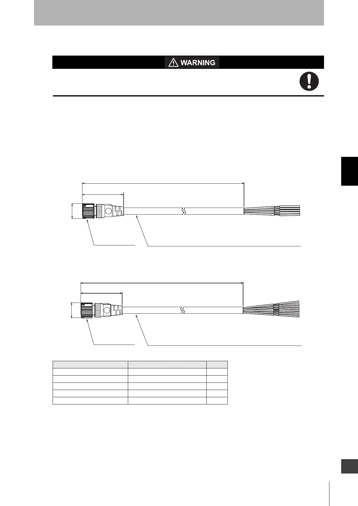
4-5-3-1. Single-Ended Cable
Single-Ended Cable for Emitter (F39-JGA-L, sold separately)
Single-Ended Cable for Receiver (F39-JGA-D, sold separately)
Emitter cable (Gray) Receiver cable (Black) L (m)
F39-JG3A-L F39-JG3A-D 3
F39-JG7A-L F39-JG7A-D 7
F39-JG10A-L F39-JG10A-D 10
F39-JG15A-L F39-JG15A-D 15
F39-JG20A-L F39-JG20A-D 20
40.7
L
Insulated vinyl round cable dia. 6.6, 5-wire
(Cross section of conductor: 0.38 mm
2
/insulator diameter: dia. 1.2 mm)
dia.14.9
M12 IP67 connector
(Unit: mm)
Insulated vinyl round cable dia. 6.6, 8-wire
(Cross section of conductor: 0.38 mm
2
/insulator diameter: dia. 1.2 mm)
dia.14.9
M12 IP67 connector
(Unit: mm)
L
40.7

 Loading...


