192
Chapter5 Wiring Examples(F3SG-RA Series)
F3SG-R
User’s Manual
Input/Output Circuit and Applications
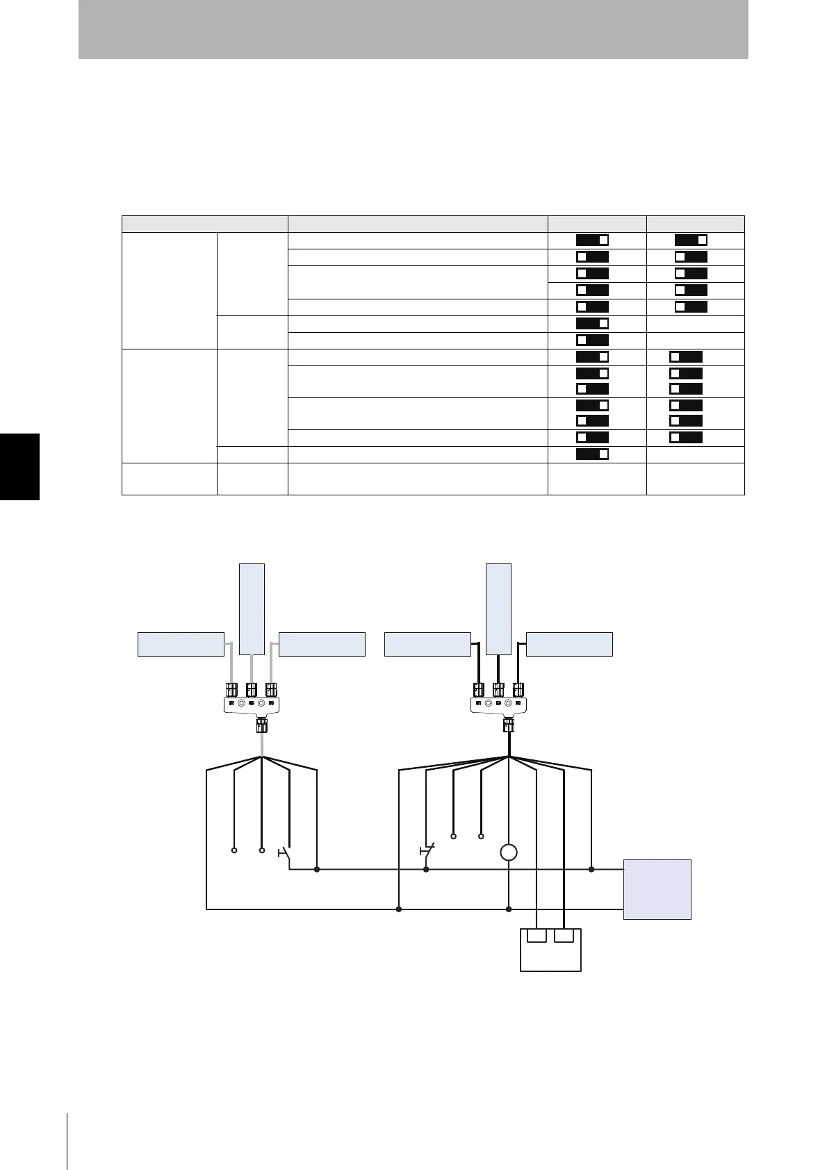
5-2-9. Standard Muting Mode with F3W-MA (T-Shaped
Configuration with 4-Joint Plug/Socket Connector)
The following is the example of F3SG-RA with Scan Code B, External Device Monitoring disabled,
Auto Reset mode, PNP output and External Test in 24 V Active, and F3W-MA with Scan Code A,
Chattering and Void Space Prevention 1, Off-Delay 100 ms and Muting Enable disabled.
[DIP Switch settings]*1
: Indicates a switch position.
Configure functions with the DIP Switches before wiring.
[Wiring Example]
Function DIP-SW1 DIP-SW2
F3SG-RA
Receiver
Scan Code B
EDM Disabled (factory default setting)
Auto Reset (factory default setting)
PNP (factory default setting)
Emitter
Scan Code B -
External Test: 24 V Active (factory default setting) -
F3W-MA
Primary
Receiver
Scan Code A *2
Chattering and Void Space Prevention 1 *2
*2
Off-Delay 100 ms *2
*2
Muting Enable Disabled (factory default setting) *2
Emitter Scan Code A -
F3W-MA
Secondary
Receiver
Emitter
-
No setting
required
No setting
required
㻟㻻㻺㻟㻻㻺
㻠㻻㻺㻠㻻㻺
㻠㻻㻺
㻟㻻㻺
㻟㻻㻺
㻠㻻㻺
㻡㻻㻺
㻠㻻㻺
㻡㻻㻺
㻢㻻㻺㻢㻻㻺
F3W-MA Receiver
(Primary)
F3W-MA Receiver
(Secondary)
F39-JG
□
A-D
F3SG-RA Receiver
F3W-MA Emitter
(Primary)
F3W-MA Emitter
(Secondary)
F39-JG
□
A-L
F3SG-RA Emitter
24 VDC:
Brown
OSSD 2:
White
OSSD 1:
Black
AUX:
Red
0 VDC:
Blue
Reset:
Yellow *3
Muting Enable:
Gray
Not used:
Pink
Not used:
Yellow
Not used:
White
0 VDC:
Blue
24 VDC:
Brown
TEST:
Black
Safety
Controller *5 *6
IN1 IN2
+24 VDC
0 VDC
Power Supply
ML
S2
S1
*4
F39-GCN4-L F39-GCN4-D
S1: Test Switch (Connect the line to 0 V if this switch is not required)
S2: Lockout/Interlock Reset Switch, Override Switch or Override Cancel Switch
ML: Muting lamp
*1. The functions are configurable with DIP Switch. For the DIP Switch of the F3SG-RA, refer to the Chapter 3 Setting with DIP
Switch. For the DIP Switch of the F3W-MA, refer to the Smart Muting Actuator F3W-MA Series User's Manual.
*2. DIP Switch Bank 2 of F3W-MA receiver is not used.
*3. Also used as Override input line.
*4. Make sure to connect an override cancel switch to the Reset line when using the override function. Otherwise the override state
may not be released by the override cancel switch, resulting in serious injury.
*5. Refer to 5-4. Connectable Safety Control Units for more information.
*6. The safety controller and the F3SG-R must share the power supply or be connected to the common terminal of the power
supply.

 Loading...


