174
Chapter4 Wiring
F3SG-R
User’s Manual
Wiring/Installation
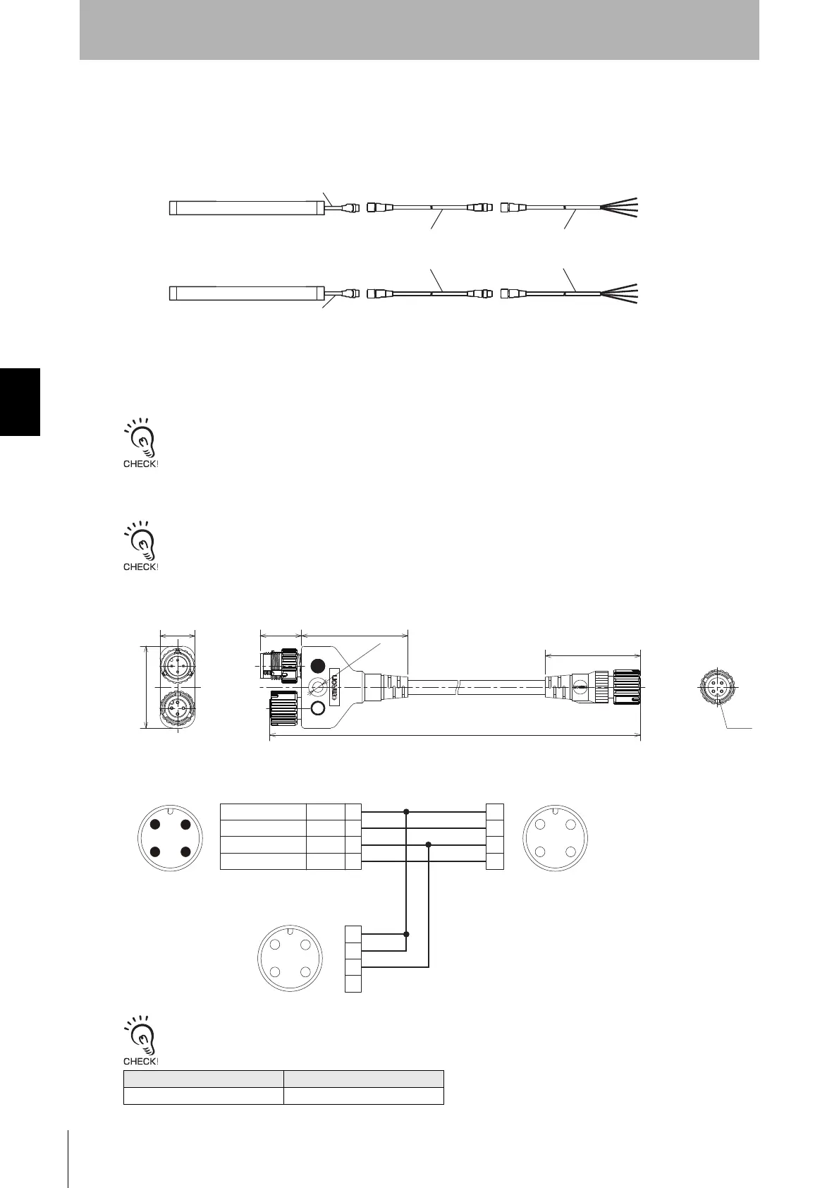
If the length of the Connector Connected to Cable, Socket on One Cable End (XS5F-D421-80-F) is
insufficient, use 1 or more Connectors Connected to Cable, Socket and Plug on Cable Ends (XS5W-
D421-81-F) to extend the length, as required. The total cable extension length of the power cable
must be 100 m max.
<Connection example>
4-5-4-2. Extending Cable Length with Commercially Available Cable
When you need to use a cable that is not specified by OMRON, use a cable that satisfies the following specifications.
1. Emitter: 4-wire Receiver: 4-wire
2. 0.3 mm
2
or larger, conductor resistance 0.058 ohms/m max.
Do not use cables in the same conduit as high voltage or electric power lines.
4-5-4-3. Reduced Wiring Connector System
Reduced wiring can be achieved by using a Y-Joint Plug/Socket Connector (F39-GCNY1, sold separately).
When using the reduced wiring connector system, the Operating Range Selection is fixed to Long Mode.
Y-Joint Plug/Socket Connector (F39-GCNY1, sold separately)
<Internal wiring diagram>
Wrong wiring causes the F3SG-RE to go to the Lockout state due to Operating Range Selection Setting error.
Model L (m)
F39-GCNY1 0.5
Emitter
Receiver
Cable is gray
Connectors Connected to Cable,
Socket and Plug on Cable Ends
(XS5W-D421-81-F)
Connector Connected to Cable,
Socket on One Cable End
(XS5F-D421-80-F)
Cable is black
4.6 dia.
17.7
40.7
15.0
500
To receiver
To control
panel side
To emitter
Plug marked with ● (blue circle): Connect to control panel side
Socket marked with ○ (open circle): Connect to emitter
1
2
3
4
FemaleMale
Connected to Single-Ended Cable or
Double-Ended cable
Connected to Power Cable or
Double-Ended Cable of F3SG-RE Emitter
Connected to Power Cable or
Double-Ended Cable of F3SG-RE Receiver
1
2
3
4
3
21
4
Female
4
12
3
3
21
4
㻝+24 VDC
OSSD 1
OSSD 2
0 V
㻞
㻟
㻠
Brown
White
Blue
Black

 Loading...


