185
F3SG-R
User’s Manual
Chapter5 Wiring Examples(F3SG-RA Series)
Input/Output Circuit and Applications
E
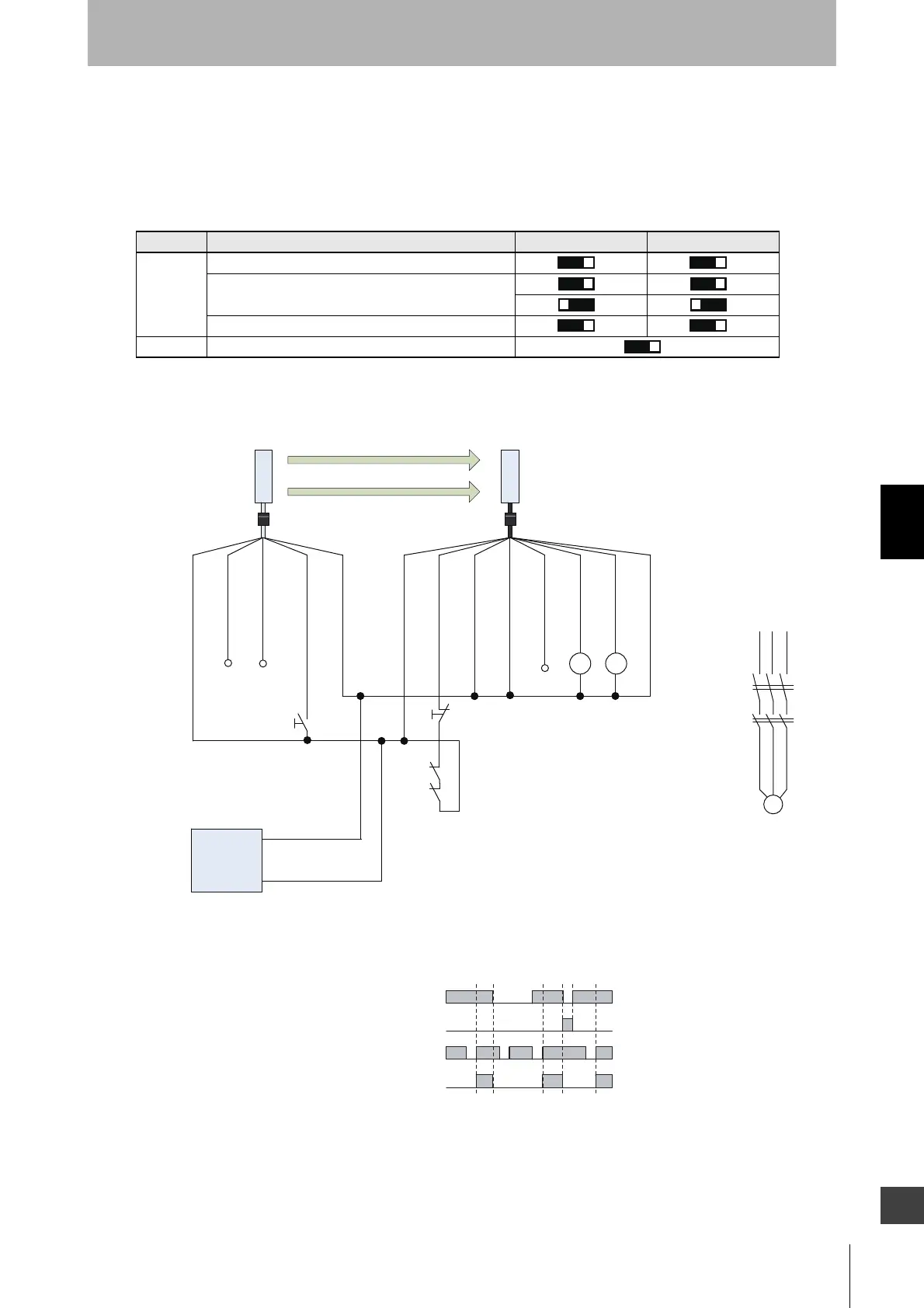
5-2-2. Standalone F3SG-RA using NPN Outputs
The following is the example of Muting not used, External Device Monitoring enabled, Manual Reset
mode, NPN output and External Test in 0 V Active.
[DIP Switch settings] *2
: Indicates a switch position.
Configure functions with the DIP Switches before wiring.
[Wiring Example]
Function DIP-SW1 DIP-SW2
Receiver
EDM Enabled
Manual Reset
NPN
Emitter External Test: 0 V Active
㻞㻻㻺
㻣㻻㻺
OSSD1 : Black
OSSD2 : White
24 VDC : Brown
Not used : Yellow
TEST : Black
Not used : White
24 VDC : Brown
0 VDC : Blue
Receiver
Emitter
0 VDC : Blue
AUX : Red
MUTE B : Pink
MUTE A : Gray
RESET : Yellow *1
S2
S1
F39-JGA-L F39-JGA-D
KM1 KM2
KM1
KM2
Power Supply
+24 VDC
0 VDC
S1: Test Switch (Connect the line to 24 V if this switch is not required)
S2: Lockout/Interlock Reset Switch
KM1, KM2: Safety relay with forcibly guided contacts (G7SA)
or magnetic contactor
M: 3-phase motor
KM1
KM2
M
Unblocked
Blocked
Test Switch (S1)
Reset Switch (S2)
OSSD
Beam state
*1. Also used as EDM input line.
*2. The functions are configurable with DIP Switch. Refer to
Chapter 3 Setting with DIP Switch for more information on
setting the functions by the DIP Switch.

 Loading...


