109
F3SG-R
User’s Manual
Chapter3 DIP Switch
Setting with DIP Switch
E
3-2. DIP Switch
Make sure to test the operation of the F3SG-R after setting with DIP Switch to verify that the
F3SG-R operates as intended. Make sure to stop the machine until the test is complete.
Unintended settings may cause a person to go undetected, resulting in serious injury or death.
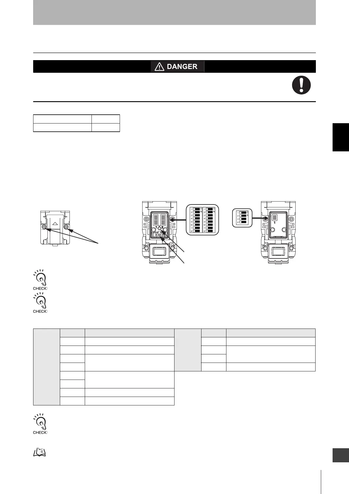
F3SG-RA series has DIP Switches to configure functions. Configure functions with the DIP Switches before
installing F3SG-RA in your site. To set DIP Switches, turn the power of the F3SG-RA off and open the cover
as shown below. When the setting the DIP Switch is complete, close the cover and turn the power of the
F3SG-RA on.
Cascaded sensors is operated based on the DIP Switches setting of the primary sensor. The DIP Switch
setting of a secondary sensor does not affect the operation.
When attaching the cover, tightly fasten the screws (M2.5, recommended torque: 0.35N.m). Failure to do so may cause the cover
to come loose, leading to deterioration of the protective functions.
The Spatter Protection Cover (F39-HGA, sold separately) extends over the DIP Switch cover of the F3SG-RA. Be sure to use the
Spatter Protection Cover only after all required settings are made to the DIP Switch.
For F3SG-RA series, the following functional settings are available by DIP Switches and Push Switch.
Operate the DIP Switch before turning the power of the F3SG-RA on.
If the DIP Switch is operated during operation of the F3SG-RA, the F3SG-RA transitions to lockout.
A change of the DIP Switch setting is activated upon power-on or lockout reset.
Note that do not use any tool which may damage F3SG-RA’s body when operating the DIP Switch.
For lockout reset function, see 2-8. Lockout Reset.
F3SG-RA Series X
F3SG-RE Series
Receiver Position Function Emitter Position Function
1 Scan Code 1 Scan Code
2 External Device Monitoring (EDM) 2 Operating Range Selection
3 Interlock/Pre-Reset 3
4 4 External Test
5 Fixed Blanking/Floating Blanking
6
7 PNP/NPN Selection
8 DIP Switch/Configuration Tool Selection
Receiver Emitter
Factory Default Setting
Push Switch
Communication Port
Screw(M2.5)
DIP Switch
(Cover is closed)

 Loading...


