201
F3SG-R
User’s Manual
Chapter5 Wiring Examples (F3SG-RE Series)
Input/Output Circuit and Applications
E
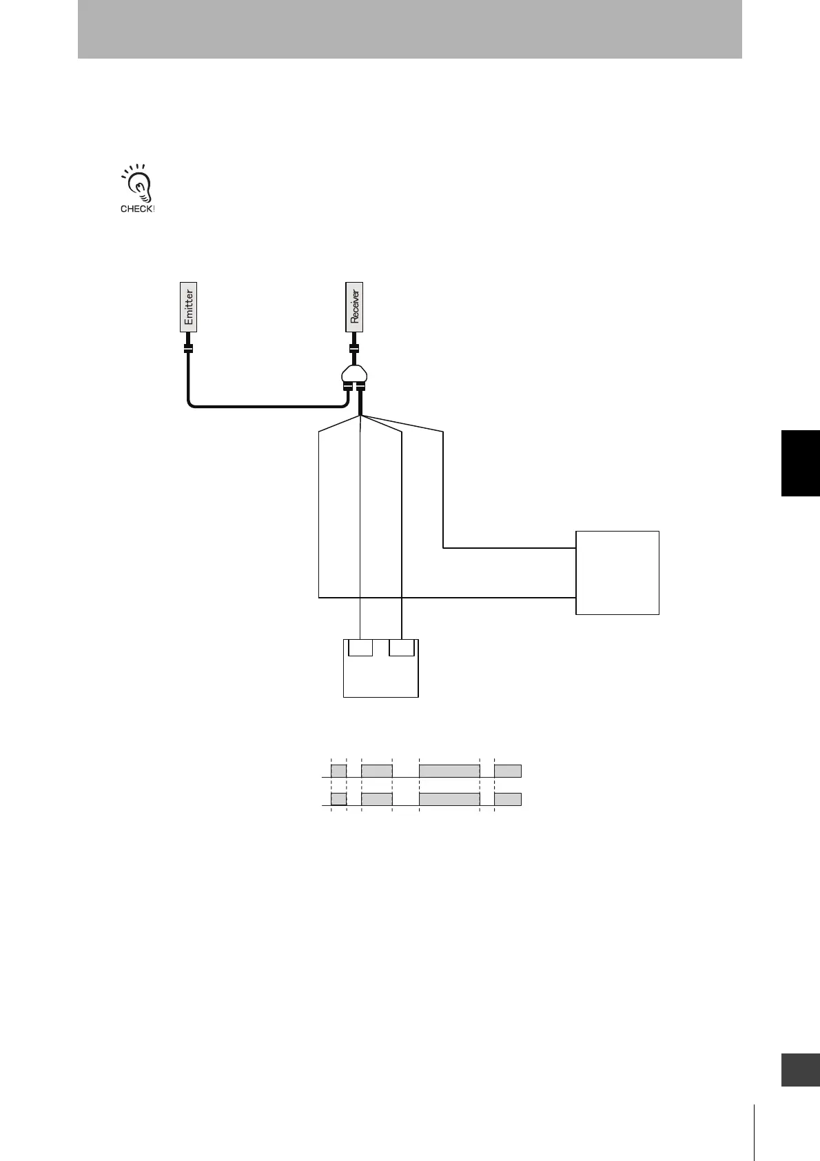
5-3-3. Standalone F3SG-RE with Y-Joint Plug/Socket
Connector
When using the reduced wiring connector system, the Operating Range Selection is fixed to Long Mode.
Wrong wiring causes the F3SG-RE to go to the Lockout state due to Operating Range Selection Setting error. Make sure
that the cables are properly wired to the connector, referring to 4-5-4-3. Reduced Wiring Connector System.
0 VDC: Blue
OSSD1: Black
OSSD2: White
24 VDC: Brown
+24V DC
0V
XS5W-D42
-
81-
F39-GCNY1
XS5F-D42-80-
IN1 IN2
Safety
Controller *1*2
Power supply
Unblocked
Blocked
OSSD
Beam state
*1. Refer to 5-4. Connectable Safety Control Units
for more information.
*2. The safety controller and the F3SG-RE must
share the power supply or be connected to the
common terminal of the power supply.

 Loading...


