197
F3SG-R
User’s Manual
Chapter5 Wiring Examples(F3SG-RA Series)
Input/Output Circuit and Applications
E
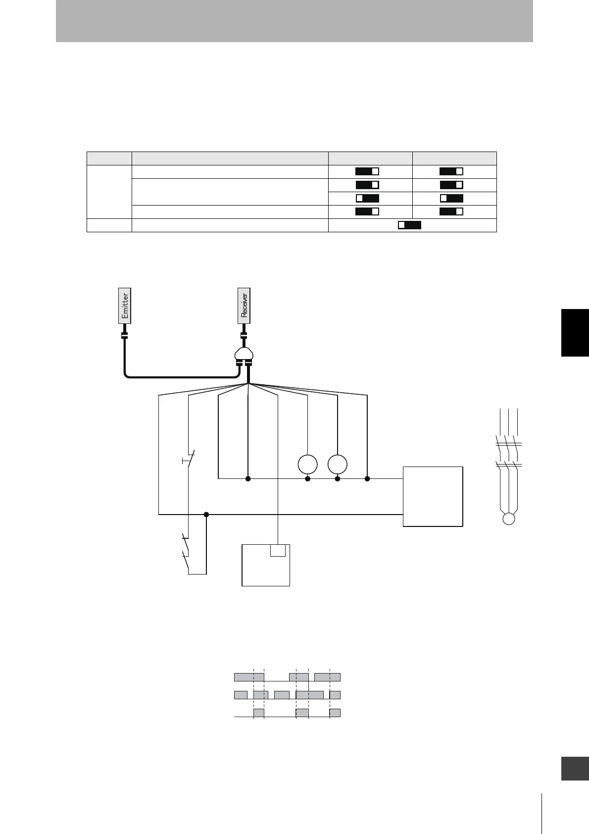
5-2-14. Standalone F3SG-RA with Y-Joint Plug/Socket
Connector using NPN outputs
The following is the example of Muting not used, External Device Monitoring enabled, Manual Reset
mode, NPN output and External Test in 24 V Active.
[DIP Switch settings] *3
: Indicates a switch position.
Configure functions with the DIP Switches before wiring.
[Wiring Example]
Function DIP-SW1 DIP-SW2
Receiver
EDM Enabled
Manual Reset
NPN
Emitter External Test: 24 V Active (factory default setting)
㻞㻻㻺
㻟㻻㻺 㻟㻻㻺
㻠㻻㻺 㻠㻻㻺
㻣㻻㻺
KM1
KM2
M
0 VDC: Blue
RESET:
Yellow*1
MUTE A: Gray
MUTE B: Pink
AUX: Red
OSSD1: Black
OSSD2: White
24 VDC: Brown
+24 VDC
0 VDC
Power supply
IN
PLC
*2
KM1 KM2
KM1
KM2
F39-JG
B-L
F39-GCNY2
F39-JG
A-D
S1
S1: Lockout/Interlock Reset Switch
KM1,KM2: External device feedback
M: 3-phase motor
PLC: Programmable controller
(Used for monitoring only. NOT related to safety system.)
Unblocked
Blocked
Reset Switch (S1)
OSSD
Beam state
*1. Also used as EDM input line.
*2. When connecting to the PLC, the output mode must be
changed with the Configuration Tool.
*3. The functions are configurable with DIP Switch. Refer to
Chapter 3 Setting with DIP Switch for more information on
setting the functions by the DIP Switch.

 Loading...


