125
F3SG-R
User’s Manual
Chapter4 Installation Considerations
Wiring/Installation
E
• P: Beam Gap (mm)
F3SG-RA-14 . . . 10 mm
F3SG-RA-30 . . . 20 mm
Refer to 1-6-1. List of Models/Response Time/
Current Consumption/Weight for total number of
F3SG-R beams.
4-1-2-2. Safety Distance Formulas according to ANSI B11.19
If a person approaches the detection zone of the F3SG-R orthogonally, calculate the safety distance as
shown below.
S = K x (Ts + Tc + Tr + Tbm) + Dpf
• S: Safety distance
• K: Approach speed to the detection zone (the value recommended by OSHA standard is 1,600 mm/
s)
Approach speed K is not specified in the ANSI B.11.19 standard. To determine the value of K to apply,
consider all factors, including the operator's physical ability.
• Ts = Machine's stopping time (s)
• Tr = Response time of the F3SG-R from ON to OFF (s)
• Tc = Machine control circuit's maximum response time required to activate its brake (s)
• Tbm = Additional time (s)
If a machine has a brake monitor, "Tbm= Brake monitor setting time - (Ts + Tc)". If it has no brake
monitor, we recommend using 20% or more of (Ts + Tc) as additional time.
• Dpf = Additional distance
According to ANSI's formula, Dpf is calculated as shown below:
Dpf = 3.4 x (d - 7.0): Where d is the detection capability (or object resolution) of the F3SG-R (unit: mm)
[Calculation example]
When K = 1,600 mm/s, Ts + Tc = 0.06 s, brake monitor setting time = 0.1 s,
Tr = 0.008 s, and d = 14 mm:
Tbm = 0.1 - 0.06 = 0.04 s
Dpf = 3.4 x (14 - 7.0) = 23.8 mm
S = 1,600 x (0.06 + 0.008 + 0.04) + 23.8 = 196.6 mm
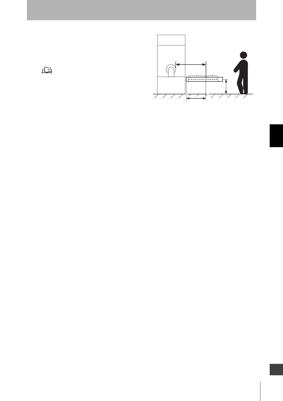
H
Safety
distance (S)
Hazard
Distance L from casing end
to detection zone
Detection
zone
Warning
zone

 Loading...


