124
Chapter4 Installation Considerations
F3SG-R
User’s Manual
Wiring/Installation
• Tm: Machine's response time (s)
• Ts: Response time of the F3SG-R from ON to OFF (s)
• a: Height of machine hazardous zone (mm)
• b: Height of upper edge of detection zone (mm)
When Tm = 0.05 s, Ts = 0.008 s, a = 1,400 mm, b = 1,500 m:
From the table above, Cro = 850 mm. Since b is between 1,400 mm and 1,600 mm, b = 1,400
mm which has the greater Cro value, shall be used.
S = 2,000 mm/s × (0.05 s + 0.008 s) + 850 mm
= 966 mm
Since 966 mm is greater than 500 mm, use K = 1,600 mm/s and recalculate it.
S = 1,600 m/s × (0.05 s + 0.008 s) + 850 mm
= 942.8 mm
Since S = 942.8 mm is greater than S = 116 mm calculated by the calculation example of
Detection Zone Orthogonal to Direction of Approach, the required safety distance S is 942.9 mm.
Refer to Detection Zone Orthogonal to Direction of Approach under 4-1-2-1. Safety Distance
Formulas according to ISO 13855/EN ISO 13855.
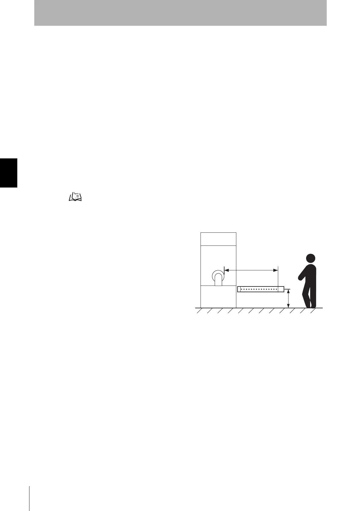
Detection Zone Parallel to Direction of Approach
Use K = 1,600 mm/s and C = (1200 - 0.4 x H) in
formula (1) for calculation. Note that C must not be
less than 850 mm.
S = 1,600 mm/s x (Tm + Ts) + 1200 - 0.4 x H
• S = Safety distance (mm)
• Tm = Machine's response time (s)
• Ts = Response time of F3SG-R from ON to OFF
(s)
• H = Installation height (mm)
Note that H must satisfy:
1000 >= H >= 15 (d - 50 mm)
Also, you must include a hazardous condition under which a person may go through under a detection
zone if H exceeds 300 mm (200 mm for other purpose than industrial use) into risk assessment.
[Calculation example]
When Tm = 0.05 s, Ts = 0.08 s, and d = 14 mm:
S = 1,600 mm/s x (0.05 s + 0.08 s) + 1200 - 0.4 x 500 mm
= 1092.8 mm
When a warning zone is configured as in the figure, you must calculate L, a distance from an end of
casing to a detection zone, using a formula below:
L = (Total number of F3SG-R beams - number of warning zone beams - 1) x P + 10
+
Safety distance (S)
Hazard

 Loading...


