123
F3SG-R
User’s Manual
Chapter4 Installation Considerations
Wiring/Installation
E
be determined by comparison of the calculated values in Detection Zone Orthogonal to Direction of
Approach. The greater value resulting from this comparison shall be applied.
S=(K × T) + Cro . . . Formula (4)
• S: Safety distance
• K: Approach speed to the detection zone
• T: Total response time of the machine and FSG-R
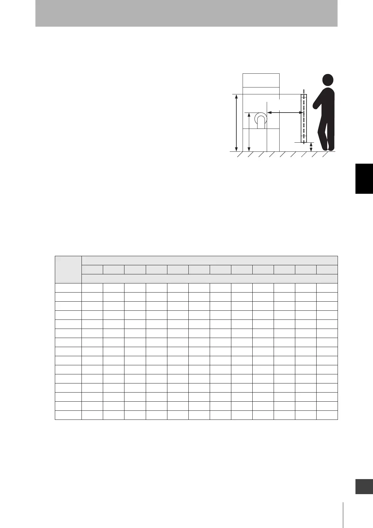
• Cro: Approach distance based on the distance which
personnel can move towards the hazardous zone of a
machine by reaching over the detection zone. The distance
is determined in the table below based on the height of the
hazardous zone, a, and the height of the upper edge of the
detection zone, b.
Note: Lower edge of the detection zone above 300 mm in
relation to the reference plane does not offer sufficient
protection against crawling below.
First, use K = 2,000 mm/s in formula (4) for the calculation. If the result of this calculation is less than
100 mm, use S = 100 mm.
If the result exceeds 500 mm, use K = 1,600 mm/s to recalculate it. If the result of the recalculation is
less than 500 mm, use S = 500 mm.
Note 1. Upper edge of the detection zone below 900 mm is not included since they do not offer
sufficient protection against circumventing or stepping over.
Note 2. When determining the values of this table, it shall not be interpolated. If the known values a, b
or Cro are between two values of this table, the greater safety distance shall be used.
[Calculation example]
• T: Tm + Ts (s)
Height of
hazardou
s zone, a
Height of upper edge of detection zone, b
900 1000 1100 1200 1300 1400 1600 1800 2000 2200 2400 2600
Additional distance to hazardous zone, Cro
2600 000000000000
2500 400 400 350 300 300 300 300 300 250 150 100 0
2400 550 550 550 500 450 450 400 400 300 250 100 0
2200 800 750 750 700 650 650 600 550 400 250 0 0
2000 950 950 850 850 800 750 700 550 400 0 0 0
1800 1100 1100 950 950 850 800 750 550 0 0 0 0
1600 1150 1150 1100 1000 900 850 750 450 0 0 0 0
1400 1200 1200 1100 1000 900 850 650 0 0 0 0 0
1200 1200 1200 1100 1000 850 800 0 0 0 0 0 0
1000 1200 1150 1050 950 750 700 0 0 0 0 0 0
800 1150 1050 950 800 500 450 0 0 0 0 0 0
600105095075055000000000
4009007000000000000
20060000000000000
0 000000000000
Hazard
Safety
distance (S)
Reference plane
a
b
300 mm max.

 Loading...


