168
Chapter4 Wiring
F3SG-R
User’s Manual
Wiring/Installation
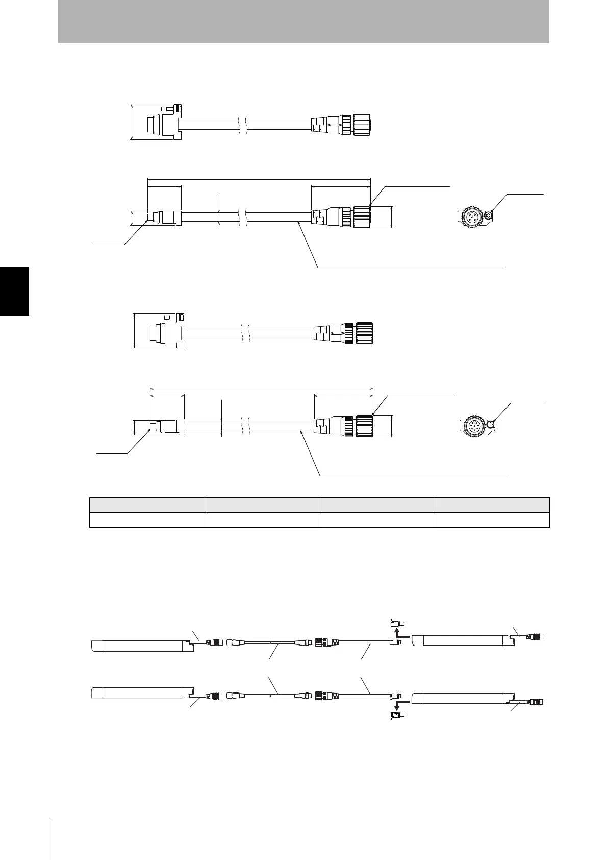
4-5-3-3. Cascading Cable
Cascading Cable for Emitter (F39-JGR2W-L, sold separately)
Cascading Cable for Receiver (F39-JGR2W-D, sold separately)
If the length of the Cascading Cable is insufficient, connect the F39-JGB Double-Ended Cable
between the power cable of the F3SG-RA and the F39-JGR2W Cascading Cable, as required. (Cable
length between sensors: 10 m max.)
Set model name Emitter cable (Gray) Receiver cable (Black) L (m)
F39-JGR2W F39-JGR2W-L F39-JGR2W-D 0.2
200
dia. 14.9
40.7
dia. 6
23.4
10
Insulated vinyl round cable dia. 6 mm, 5-wire
(Cross section of conductor: 0.15 mm
2
/Insulator diameter: dia. 1 mm)
Connector
M12 IP67 Connector
24.2
M2.5 screw
200
dia. 14.9
40.7
dia. 6
23.4
10
Insulated vinyl round cable dia. 6 mm, 8-wire
(Cross section of conductor: 0.15 mm
2
/Insulator diameter: dia. 1 mm)
Connector
M12 IP67 Connector
24.2
M2.5 screw
F3SG-RA Emitter
F3SG-RA Receiver
Cable is gray
Model F39-JG
B-L(Gray)
Double-Ended Cable
Model F39-JG
B
Cable is black
Model F39-JG
B-D(Black)
Cascading Cable
Model F39-JGR2W
F3SG-RA Emitter
F3SG-RA Receiver
Cable is gray
Cable is black
Remove the cap
Remove the cap

 Loading...


