169
F3SG-R
User’s Manual
Chapter4 Wiring
Wiring/Installation
E
4-5-3-4. Extending Cable Length with Commercially Available Cable
When you need to use a cable that is not specified by OMRON, use a cable that satisfies the following
specifications.
1. Emitter: 5-wire Receiver: 8-wire
2. 0.3 mm
2
or larger, conductor resistance 0.058 ohms/m max.
3. Mute A and Mute B lines, and 24 VDC and 0 VDC lines must be used as twisted-pair lines.
Do not use cables in the same conduit as high voltage or electric power lines.
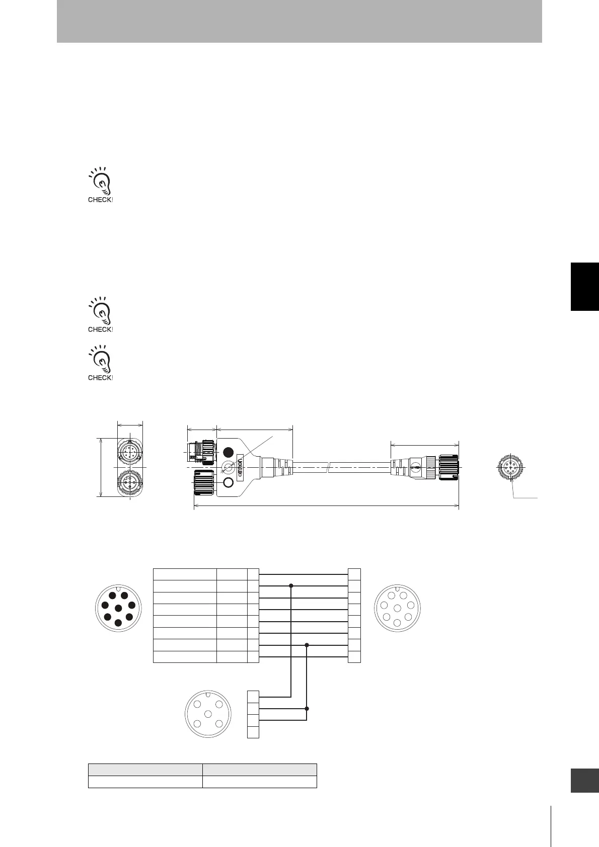
4-5-3-5. Reduced Wiring Connector System with Y-Joint Plug/Socket
Connector
Reduced wiring can be achieved by using a Y-Joint Plug/Socket Connector (F39-GCNY2, sold
separately).
When using the reduced wiring connector system, the External Test cannot be used.
Make sure the Position 4 of the emitter's DIP Switch is set to 24 V Active.
Y-Joint Plug/Socket Connector (F39-GCNY2, sold separately)
<Internal wiring diagram>
Model L (m)
F39-GCNY2 0.5
17.7 45.5
40.7
15.0
35.0
M12 x 1
4.6 dia.
To control
panel side
To emitter
To receiver
Plug marked with ● (blue circle): Connect to control panel side
Socket marked with ○ (open circle): Connect to emitter
5
8
4
3
2
1
7
6
5
8
6
7
1
2
3
4
1
2
3
4
5
6
7
8
FemaleMale
Connected to Single-Ended Cable or
Double-Ended Cable of F3SG-RA Receiver
Connected to Power Cable or
Double-Ended Cable of F3SG-RA Emitter
Connected to Power Cable or
Double-Ended Cable of F3SG-RA Receiver
1
2
3
4
5
3
21
4
Female
1RESET
+24 VDC
MUTE A
MUTE B
OSSD 1
OSSD 2
0 V
AUX
2
3
4
5
6
7
8
Yellow
Brown
Gray
Pink
Black
White
Blue
Red

 Loading...


