183
F3SG-R
User’s Manual
Chapter5 Input/Output Circuit
Input/Output Circuit and Applications
E
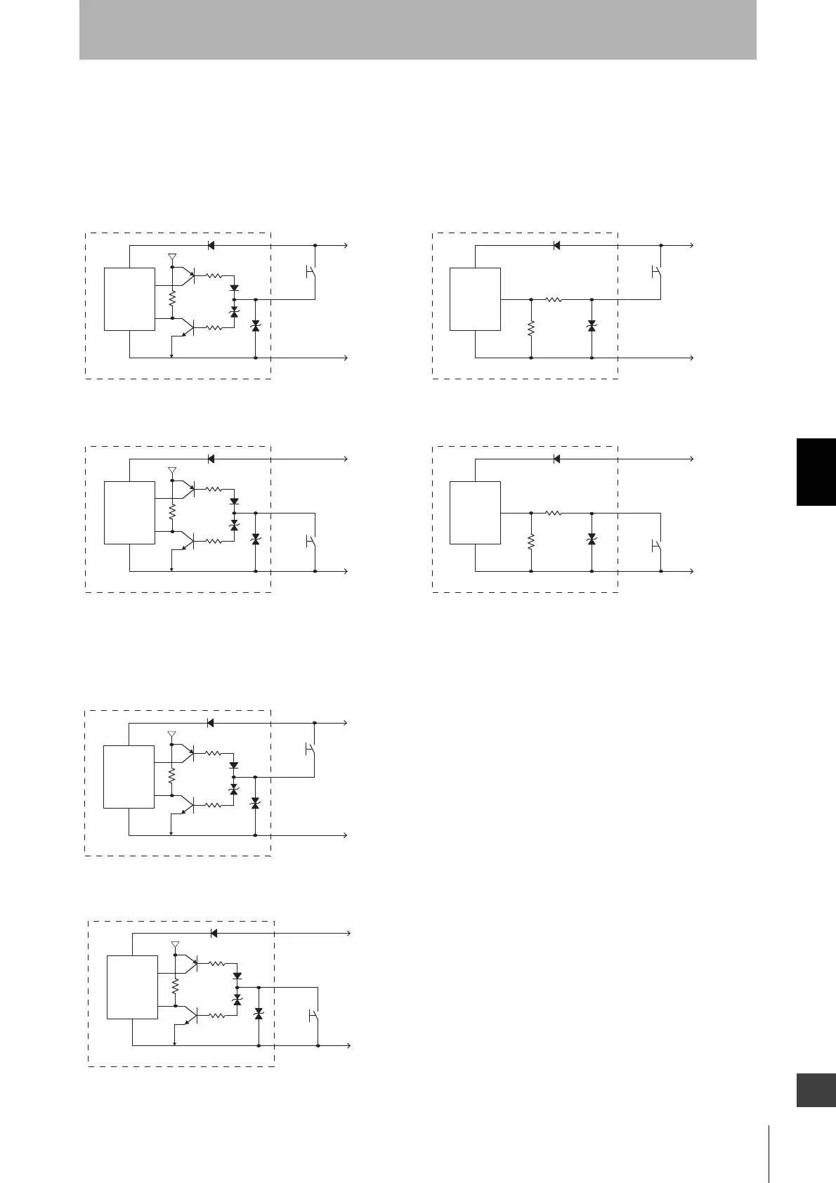
5-1-2. Input Circuit Diagram by Function
The input circuit diagrams of by function are shown below.
5-1-2-1. F3SG-RA Series
PNP Output
NPN Output
5-1-2-2. F3SG-RE Series
PNP Output
NPN Output
Emitter
Main
Circuit
+24 VDC
0 VDC
5 V
Short circuit current:
3 mA
<Input circuit (Test input)>
Receiver
Main
Circuit
+24 VDC
0 VDC
Short circuit current *
<Input circuit (Reset input, Muting inputs A/B)>
Receiver
Main
Circuit
+24 VDC
0 VDC
Short circuit current *
<Input circuit (Reset, Muting inputs A/B)>
Emitter
Main
Circuit
+24 VDC
0 VDC
5 V
Short circuit current:
3 mA
<Input circuit (Test input)>
*Short circuit current: 5mA (Reset input), 3mA
㸦
Muting inputs A/B
㸧
Emitter
Main
Circuit
+24 VDC
0 VDC
5 V
Short circuit current:
3 mA
<Input circuit (Operating Range Select Input)>
Emitter
Main
Circuit
+24 VDC
0 VDC
5 V
Short circuit current:
3 mA
<Input circuit (Operating Range Select Input)>

 Loading...


