110
Chapter3 DIP Switch
F3SG-R
User’s Manual
Setting with DIP Switch
3-2-1. DIP Switch on Receiver
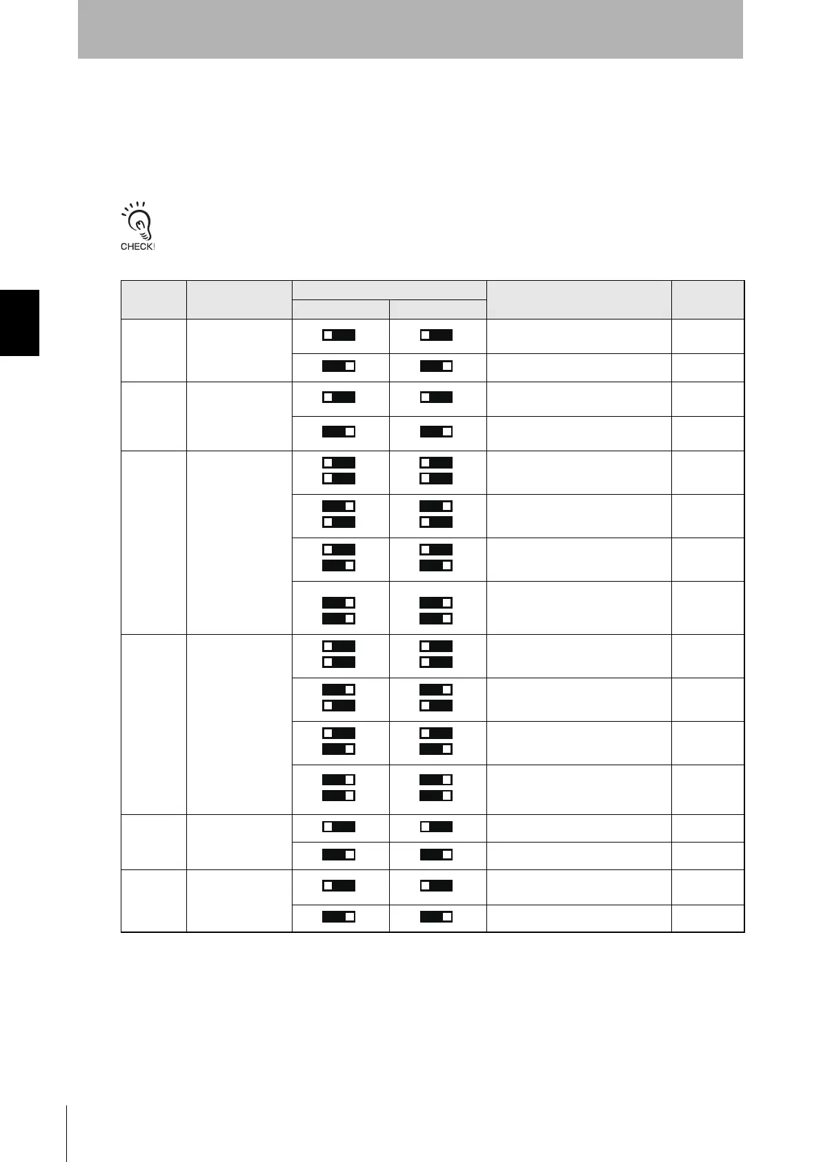
The following functional settings are available by DIP Switches on the receiver. A receiver has two DIP
Switches, both of which must be configured based on the table below. For functional details, see
respective chapter in the Functional Details column.
If the settings of two DIP Switches are different, when the power is turned on, F3SG-RA transitions to lockout.
: Indicates a switch position.
You can configure the receiver's DIP Switch position 8 whether the setting of the DIP Switch or the
Configuration Tool should be enabled. If you want to use the Configuration Tool to change the setting,
configure the Position 8 setting as Configuration Tool Enabled. This setting ignores the DIP Switch
setting.
Settings changed with the Configuration Tool are stored in the internal memory of the F3SG-RA. When
any change is made to the settings and then the Position 8 is set to OFF, the F3SG-RA operates
Position Function
Setting
Description
Functional
Details
DIP-SW1 DIP-SW2
1 Scan Code
Scan Code A (factory default
setting)
2-4
Scan Code B
2-4
2
External Device
Monitoring (EDM)
External Device Monitoring (EDM)
Disabled (factory default setting)
2-11
External Device Monitoring (EDM)
Enabled
2-11
3, 4 Interlock/Pre-Reset
Auto Reset (factory default setting)
2-9
Manual Reset
(Start/Restart Interlock)
2-9
Pre-Reset
2-10
Auto Reset (same as factory default
setting)
2-9
5, 6
Fixed Blanking/
Floating Blanking
Blanking Disabled (factory default
setting)
-
Fixed Blanking Enabled
2-15
Floating Blanking Enabled
2-16
Blanking Disabled
(Same as Blanking Disabled
(factory default setting))
-
7 PNP/NPN Selection
PNP (factory default setting)
2-5
NPN
2-5
8
DIP Switch/
Configuration Tool
Selection
DIP Switch Enabled (factory default
setting)
See below.
Configuration Tool Enabled
See below.
㻝㻻㻺
㻝㻻㻺
㻞㻻㻺
㻠㻻㻺
㻟㻻㻺
㻟㻻㻺
㻠㻻㻺
㻟㻻㻺
㻠㻻㻺
㻟㻻㻺
㻠㻻㻺
㻡㻻㻺
㻢㻻㻺
㻡㻻㻺
㻢㻻㻺
㻡㻻㻺
㻢㻻㻺
㻣㻻㻺
㻣㻻㻺
㻤㻻㻺

 Loading...


