32
Chapter2 Lockout Reset
F3SG-R
User’s Manual
System Operation and Functions
2-8. Lockout Reset
2-8-1. Overview
When the cause of the lockout is removed, you can release the Lockout state of the F3SG-RA by using
either of the following methods.
• Cycle the power back ON
• Reset input
For the F3SG-RE, you can release the Lockout state by cycling the power back ON.
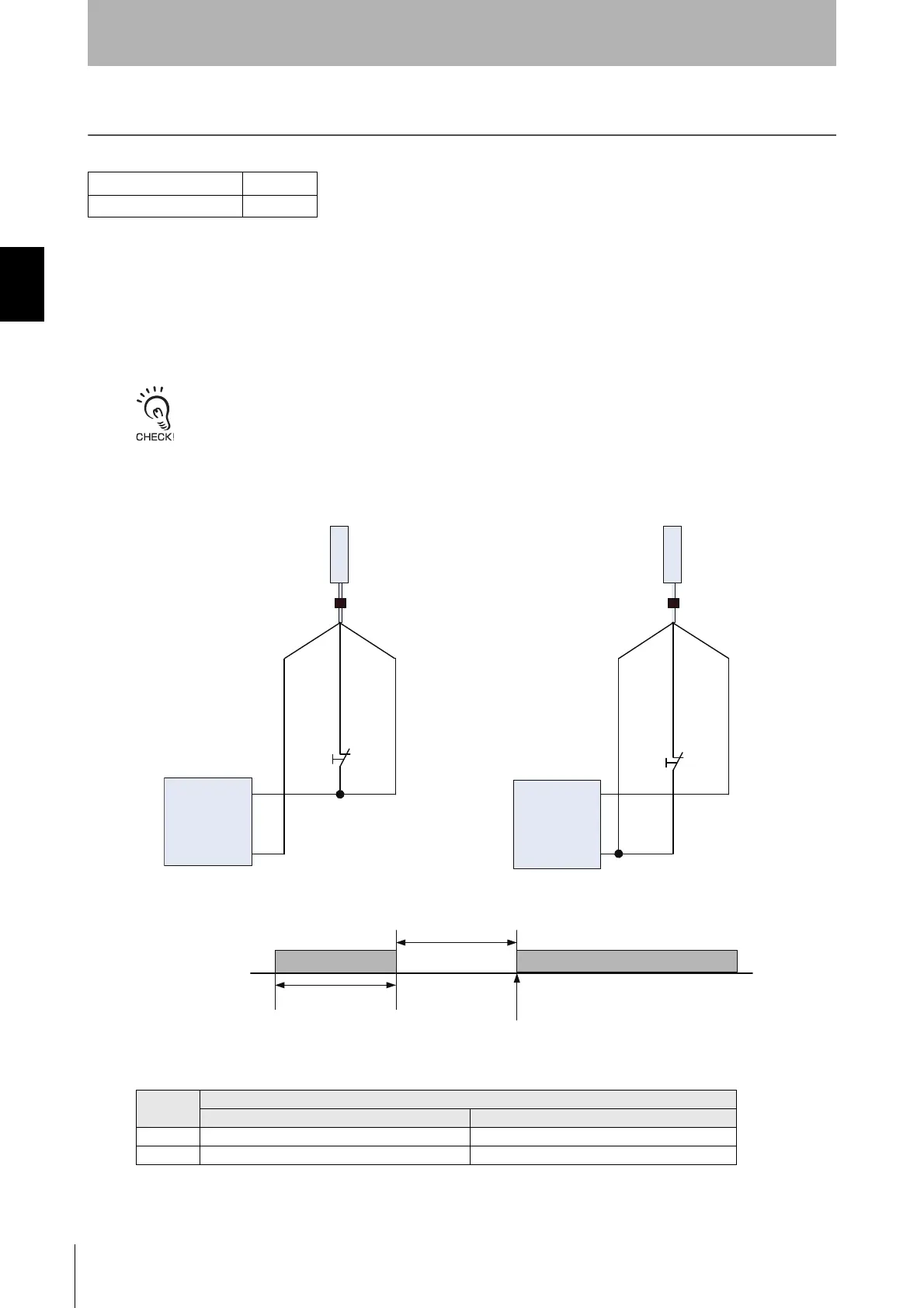
<Basic wiring diagram>
<Timing chart>
The table below shows the relation between the ON/OFF states and external lines.
F3SG-RA Series X
F3SG-RE Series
Input
External Connection
PNP NPN
ON Vs-3 V to Vs 0 to 3 V
OFF 0 V to 1/2 Vs, or open 1/2 Vs to Vs, or open
Receiver
0 VDC: Blue
RESET: Yellow
24 VDC: Brown
0 VDC: Blue
RESET: Yellow
24 VDC: Brown
S2: Lockout/InterlockReset Switch
S2: Lockout/Interlock Reset Switch
Receiver
PNP output NPN output
+24 VDC
Power Supply
0 VDC
+24 VDC
Power Supply
0 VDC
S2
S2
F39-JG
A-D F39-JG
A-D
RESET
OFF
ON
Lockout reset
1 s or more
1 s or more