10
Chapter1 LED Indicators
F3SG-R
User’s Manual
Overview and Specifications
*1. The EDM indicator is illuminated when the RESET input is in the ON state regardless of the use of
the EDM function.
*2. Refer to the timing chart of Pre-Reset mode in 2-9. Interlock for more information of blinking patterns.
*3. Muting/Override and cascade connection are not available for the F3SG-RE.
Refer to 7-3. Glossary for definitions of terms used in the table above.
TOP, CFG, LOCKOUT, STB and ON/OFF indicators are illuminated when the receiver of the F3SG-RA is
in Setting mode.
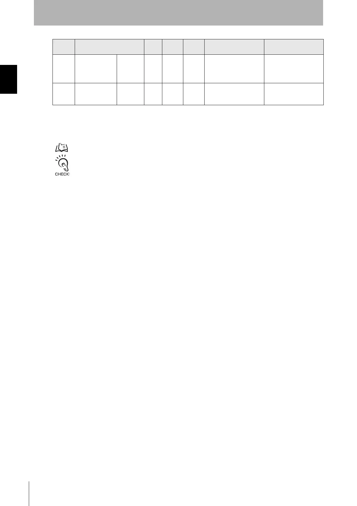
13 Communication COM Green X X
Synchronization between
emitter and receiver is
maintained
Lockout state due to
Communication error, or
error due to abnormal
power supply or noise
14
Bottom-beam-
state
BTM Blue X X
The bottom beam is
unblocked
Muting/Override state , or
Lockout state due to DIP
Switch setting error *3
Location Name of Indicator Color
F3SG-RA
Series
F3SG-RE
Series
Illuminated Blinking

 Loading...


