89
F3SG-R
User’s Manual
Chapter2 Warning Zone
System Operation and Functions
E
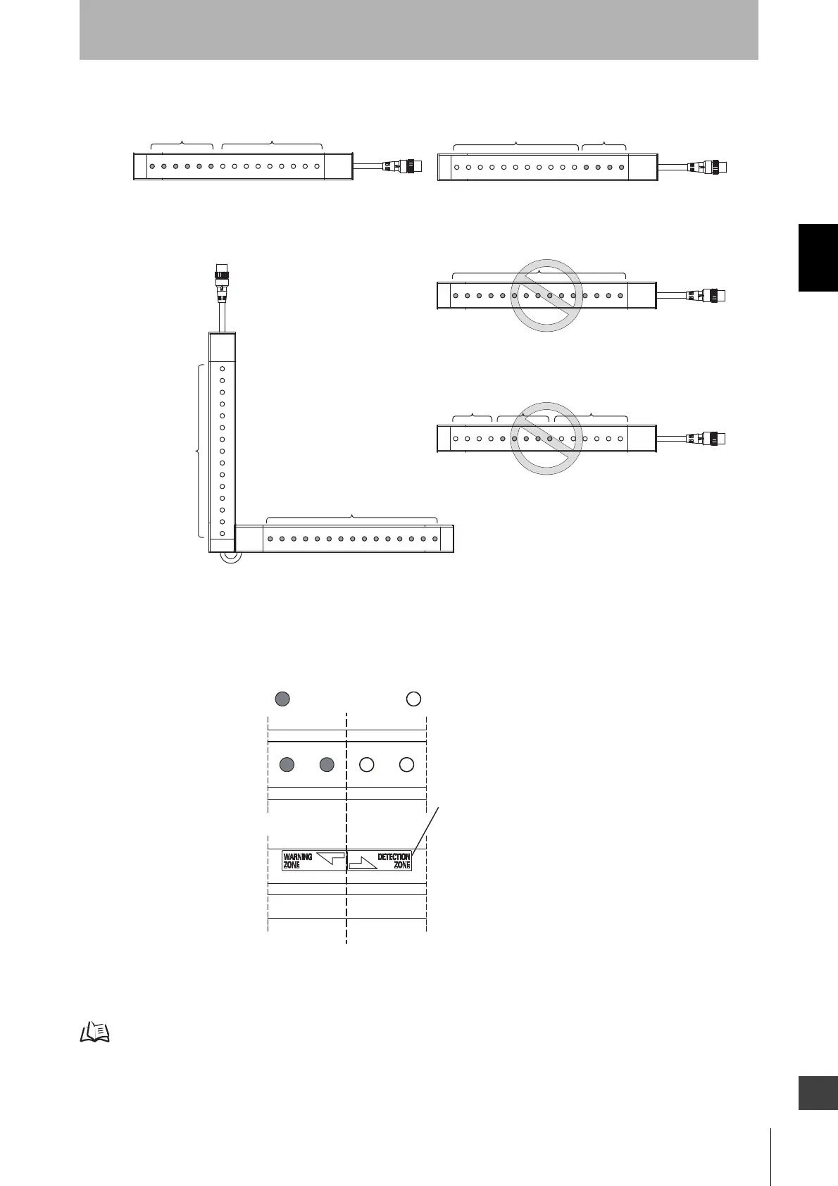
When a warning zone is configured, you must attach labels that indicate a border between normal
detection zone and warning zone.
The Blanking indicator of the F3SG-RA is illuminated when the Warning Zone is enabled.
Refer to 2-1. Combination of Functions for more information on the use in conjunction with other functions.
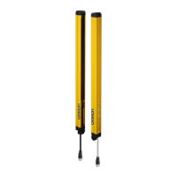
Warning Zone
Upper 6 beams
Warning Zone
Lower 4 beams
LowerUpper
Fig. 4
LowerUpper
LowerUpper
All beams are
warning zone
All beams are
detection zone
Fig. 7
Fig. 8
LowerUpper
Fig. 5
LowerUpper
Warning Zone
All beams are
warning zone
Lower
Upper
Fig. 6
Detection Zone
Detection Zone
Detection Zone
Detection Zone
Channel 2
(secondary sensor)
Channel 1
(primary sensor)
Warning
Zone
<F3SG-RA front surface>
Warning Zone Label
* Attach the Warning Zone Label
to the side surface of the F3SG-RA.
<F3SG-RA side surface>
Detection
Zone
Normal
beam
Warning
beam
 Loading...


