140
Chapter4 Dimensions
F3SG-R
User’s Manual
Wiring/Installation
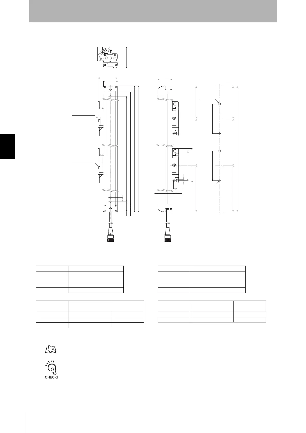
Side Mounting
4-4-3-2. Mounting with Standard Adjustable Brackets (F39-LGA)
- Use the brackets of specified quantities and locations according to the dimensions. The other brackets than described
above may not meet the specified ratings and performance.
- When you use the sensor in a situation where the sensor is under a load, increase the number of the brackets used.
- The Standard Adjustable Bracket allows beam alignment after fixing the bracket to a wall surface. The angle adjustment
range of the Standard Adjustable Brackets is ±15°.
P
D
C2 (Protective height for 14 mm)
25
15
35
48.6
C1 (Protective height for 30 mm)
A
Standard Adjustable
Bracket
Standard Adjustable
Bracket
(F39-LGA)
(F39-LGA)
50.35
72
F
42.35
A
150 max
150 max
F
150 max
150 max
6.4
9.2
72
72
84
35
2-M5 or M6
2-M5 or M6
[ Unit : mm ]
< Screw: M5 or M6 >
F3SG-RE30 Series
Dimension A C1
Dimension C1 4-digit number of the type name
(Protective height)
Dimension D C1-50
Dimension P 20
Protective height
(C1)
Number of Standard
Adjustable Brackets *
Dimension F
0190 to 1230 2 1000 mm max.
1310 to 2270 3 1000 mm max.
2350 to 2510 4 1000 mm max.
F3SG-RE14 Series
Dimension A C2+30
Dimension C2 4-digit number of the type name
(Protective height)
Dimension D C2-20
Dimension P 10
Protective height
(C2)
Number of Standard
Adjustable Brackets *
Dimension F
0160 to 1200 2 1000 mm max.
1280 to 2080 3 1000 mm max.
* The number of brackets required to mount either one of emitter and receiver.

 Loading...


