44
Chapter2 Auxiliary Output
F3SG-R
User’s Manual
System Operation and Functions
Make sure the Position 8 of the DIP Switch is set to Configuration Tool Enabled to activate the settings by the
Configuration Tool.
Refer to Safety Light Curtain Configuration Tool for Model F3SG (SD Manager 2) User’s Manual for more
information on setting this function by the Configuration Tool.
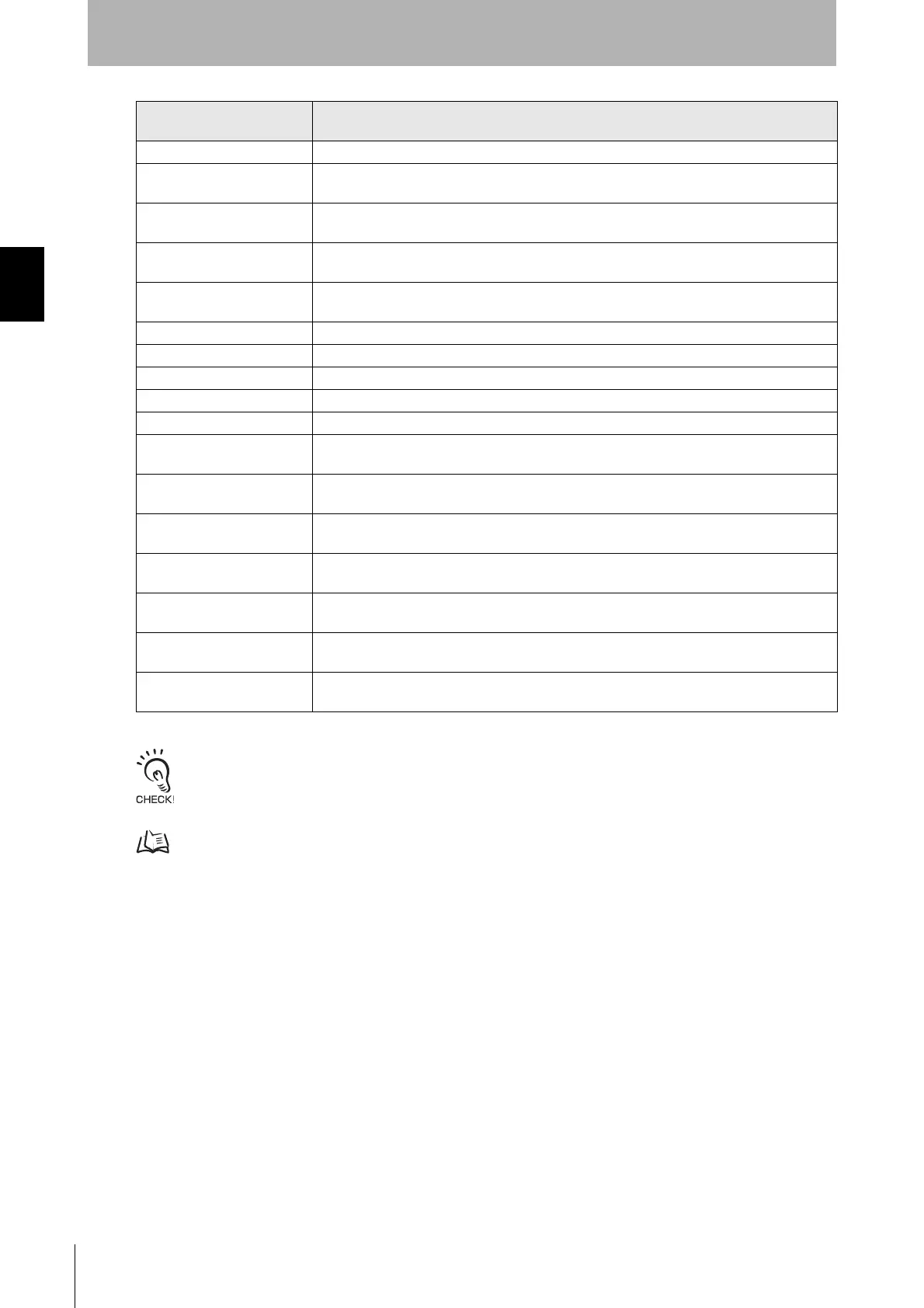
Lockout information Under error/ Lockout state
Excess power-on time
information
When power-on time exceeds power-on time threshold
Excess load switching
frequency information
When load switching frequency exceeds load switching frequency threshold
Light level diagnosis
information
When the F3SG-R is unblocked and light intensity is within a range from 100% to 170% of ON-
threshold for 10 s or longer
Blanking/Warning-zone
information
When Fixed Blanking, Floating Blanking, Reduced Resolution or Warning Zone function is
enabled
Muting information Under Muting state
Override information Under Override state
Muting/Override information Under either Muting or Override state
Sequence error information Under Muting sequence error state or Interlock sequence error state
Warning Zone Information When warning zone is interrupted
Blanking bream unblocked
information
When Fixed-Blanking or Floating Blanking beams are unblocked
Designated beam output
information
When a designated beam is blocked or unblocked
Interference/vibration
information
When the F3SG-R system stops accidentally due to interference or vibration. (In case of
cascade connection, when any of cascaded segments comes under this condition.)
Troubleshooting support
signal
When one of the signals of Sequence error information, Interference/vibration information and
Light level diagnosis information is in the ON state.
Individual cascaded sensor
output (Channel 1)
When Safety output of Primary sensor in cascade connection is the ON state
Individual Cascaded Sensor
Output (Channel 2)
When Safety output of 1st Secondary sensor in cascade connection is the ON state
Individual Cascaded Sensor
Output (Channel 3)
When Safety output of the 2nd Secondary sensor in cascade connection is the ON state
Information Name
Description
(Auxiliary output is turned ON under the following condition)

 Loading...


