52
Chapter2 Muting
F3SG-R
User’s Manual
System Operation and Functions
This distance must prevent the muting state from being enabled by a person passing through the
muting sensors.
Also, install the F3SG-R and muting sensors so that each workpiece passes through all muting
sensors before the next workpiece arrives at the first muting sensor (PNP mode).
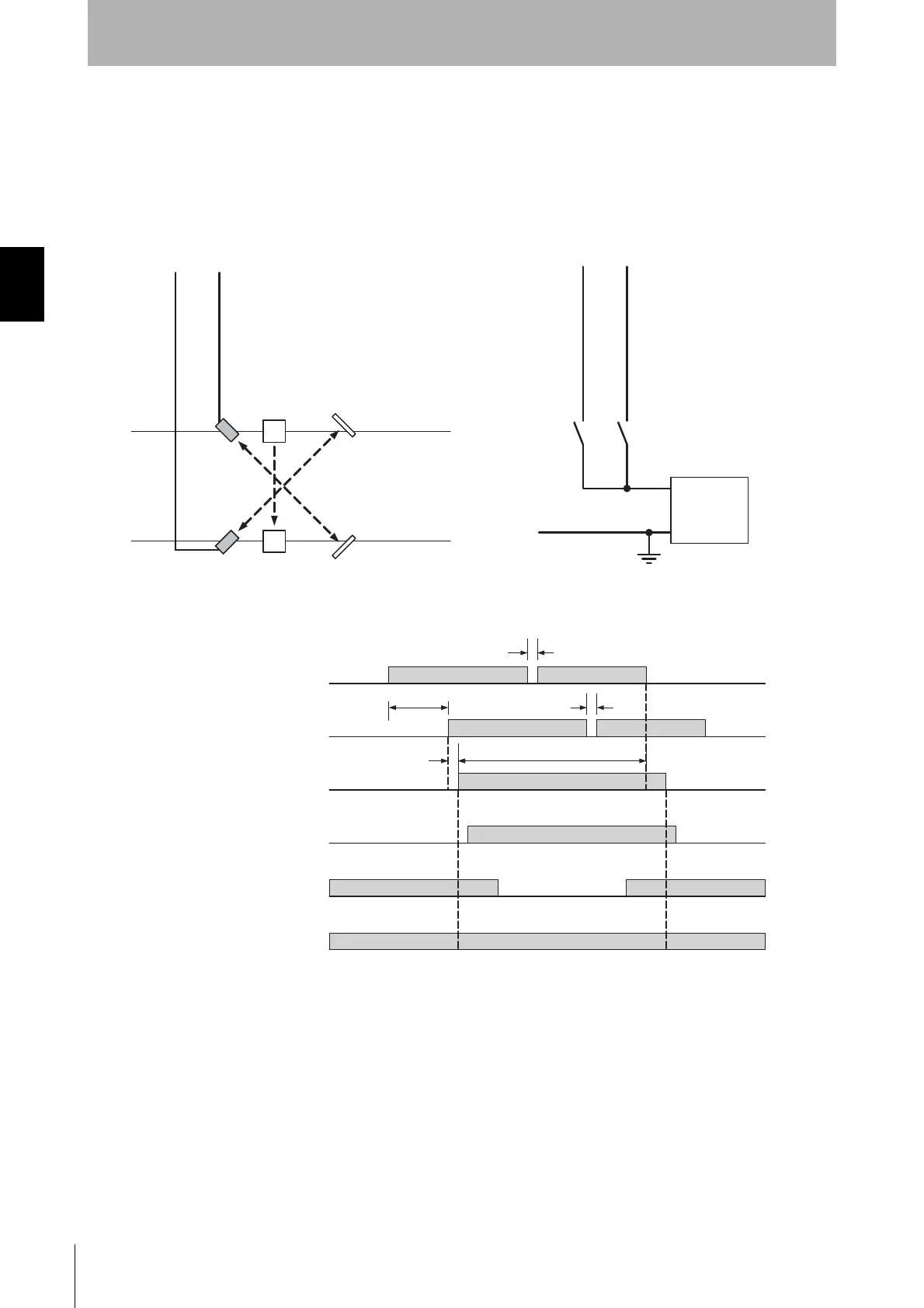
<Wiring diagram (PNP setting)>
<Timing chart>
B1 A1
+ 24 VDC
0 V
Power
supply
Muting Input B: Pink
Muting Input A: Gray
Muting Input B: Pink
Muting Input A: Gray
Reflector
Reflector A1
B1
F3SG-RA
Using a photoelectric switch as a muting sensor
Note. Two-wire type muting sensor cannot be used.
Using an N.O contact type switch as a muting sensor
A1, B1: Retro-reflective
photoelectric switch
- PNP Output
- ON when Interrupted
A1, B1: N.O. contact type switch
Muting sensor A1
ON
OFF
Muting sensor B1
Unblocked
Blocked
OSSD
ON
OFF
ON
OFF
Muting state
Enabled
Disabled
Auxiliary output
Blinking
OFF
T2 max.
Blinking at 0.5 s (1 Hz)
Beam state
T3 max.
T3 max.
T1min to T1max
80 ms max.

 Loading...


