59
F3SG-R
User’s Manual
Chapter2 Muting
System Operation and Functions
E
Wiring diagram
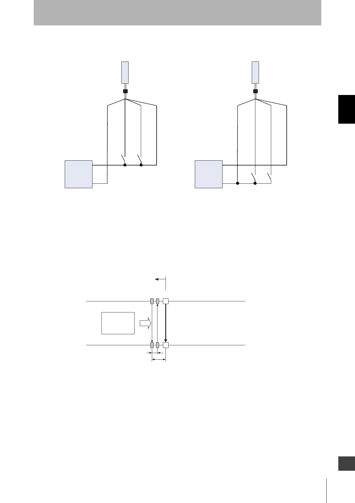
Installation Example of Exit-Only Muting Mode
This is an installation example of exit-only muting mode. When exit-only muting mode is set, install the
muting sensor on the hazardous side of the workpiece exit.
This can be used if a workpiece has a certain length and the hazardous side of the workpiece exit has
enough space around it.
1. Before a workpiece passes through
All muting sensors are turned OFF and the safety function of the F3SG-RA is working.
MUTE A : Gray
MUTE B : Pink
MUTE A : Gray
MUTE B : Pink
S1 S2
S1 S2
S1, S2:
Muting sensor
F39-JGA-D F39-JGA-D
S1, S2:
Muting sensor
PNP output NPN output
Receiver
Receiver
Power supply
0 VDC : Blue
24 VDC : Brown
0 VDC : Blue
24 VDC : Brown
0 VDC
+24 VDC
Power supply
0 VDC
+24 VDC
Workpiece
F3SG-RA
A1 B1
Hazardous zone
A1 : Muting sensor to be connected
to muting input A
B1 : Muting sensor to be connected
to muting input B
V
d2
d1

 Loading...


