73
F3SG-R
User’s Manual
Chapter2 Override
System Operation and Functions
E
Factory default setting
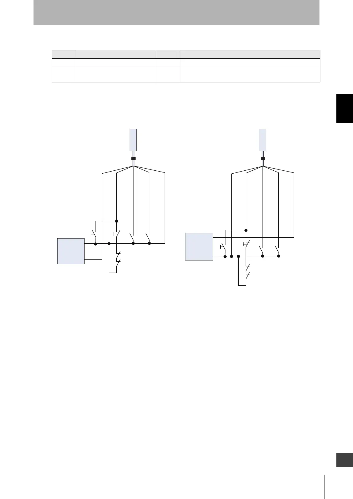
Wiring diagram
When External Device Monitoring Enabled
Variable Variable name Value Description
T1 Override input time limit 1 s Maximum input time of override input.
T2 Override time limit 600 s The duration time of the Override function. The Override state is
cancelled if it continues for longer than this time limit.
*1. Also used as Override input line.
*2. Make sure to connect an override cancel switch to
the Reset line when using the override function.
Otherwise the override state may not be released
by the override cancel switch, resulting in serious injury.
F39-JG
A-D F39-JG
A-D
S1: Lockout/Interlock Reset Switch or Override Switch
S2: Override Cancel Switch
S3, S4: Muting sensor
KM1, KM2: External device feedback
RESET : Yellow *1
S1
S2
*2
*2
S3 S4
KM1
KM2
S1
S2
S3 S4
KM1
KM2
MUTE A : Gray
MUTE B : Pink
PNP output NPN output
Receiver
Receiver
Power supply
0 VDC : Blue
24 VDC : Brown
RESET : Yellow *1
MUTE A : Gray
MUTE B : Pink
0 VDC : Blue
24 VDC : Brown
0 VDC
+24 VDC
Power supply
0 VDC
+24 VDC

 Loading...


