8-13
High-speed counter/pulse output control flag area of FP0R
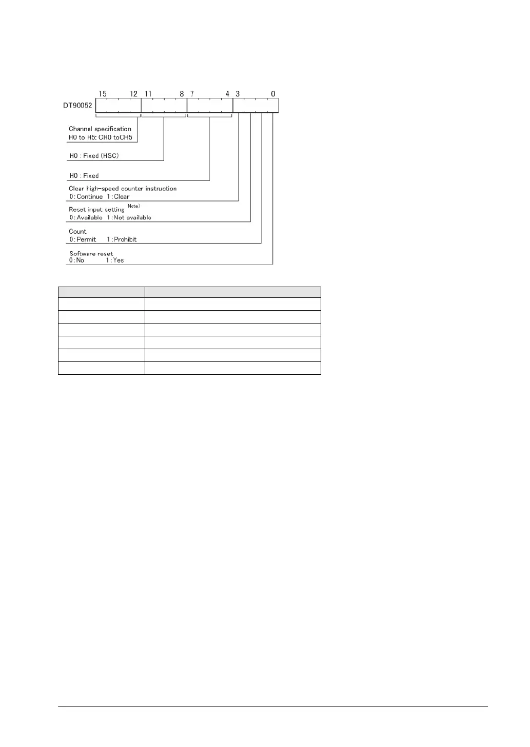
• The area DT90052 for writing channels
and control codes is allocated as shown in
the left figure.
• Control codes written with an F0 (MV)
instruction are stored by channel in
special data registers DT90370 to
DT90375.
Note) In the reset input setting, the reset
input allocated in the high-speed counter
setting of the system registers are defined
to “enable/disable”.
High-speed counter control flag monitor area
Control code flag monitor area
CH0 DT90370
CH2 DT90372
CH4 DT90374