8-12
8.3.4 I/O Allocation
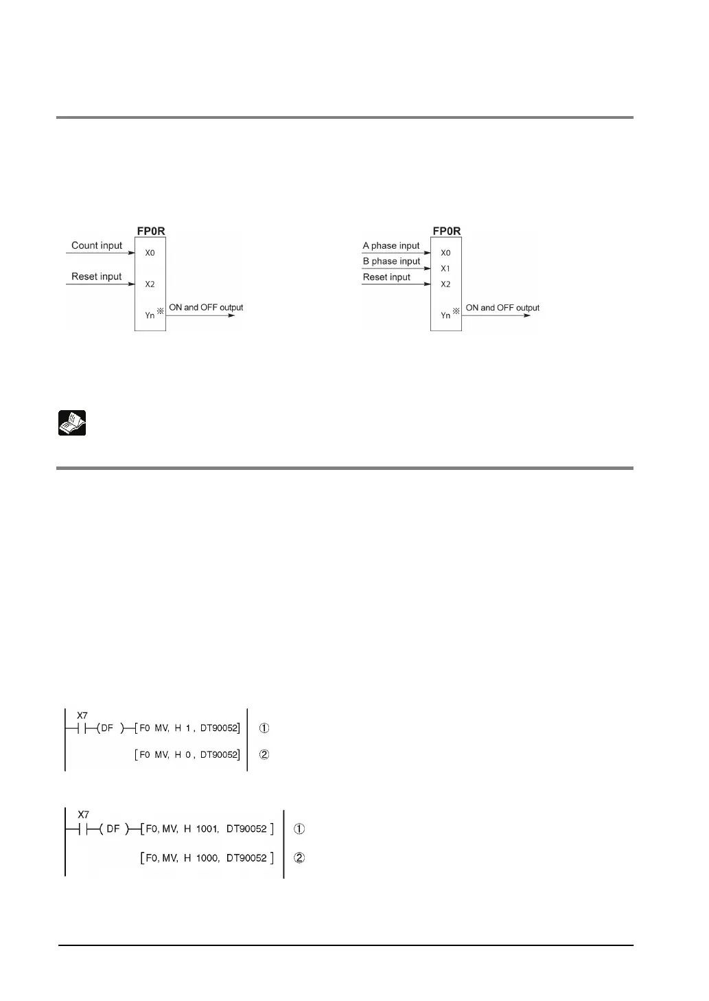
• As shown in the table in the previous section “8.2.1”, the inputs and outputs used will differ depending
on the channel number being used.
• The output turned on and off can be specified from Y0 to Y7 as desired with instructions F166 (HC1S)
and F167 (HC1R).
When using CH0 with incremental input and
When using CH0 with two-phase input and
* The output turned on and off when the target
value is reached can be specified from Y0 to Y7
as desired.
* The output turned on and off when the target
value is reached can be specified from Y0 to Y7
as desired.
Reference: <8.2.1 Table of Specifications>
8.3.5 Instructions used with High-speed Counter Function
High-speed counter control instruction (F0)
• This instruction is used for counter operations such as software reset and count disable.
• Specify this instruction together with the special data register DT90052.
• Once this instruction is executed, the settings will remain until this instruction is executed again.
Operations that can be performed with this instruction
• Counter software reset (bit0)
• Counting operation enable/disable (bit1)
• Hardware reset enable/disable (bit2)
• Clear high-speed counter instructions F166 to F167 (bit3)
• Clear target value match interrupt (bit3)
Example: Performing a software reset
In the above program, the reset is performed in step
(1) and 0 is entered just after that in step (2). The
count is now ready for operation. If it is only reset,
counting will not be performed.