8-50
8.4.15 Data Table Control Instruction (F174)
- Pulses are output from the specified channel according to the specified data table.
- Positioning is performed sequentially according to the values of data tables, and stops at the data table
that the value of pulse output stop (K0) is written.
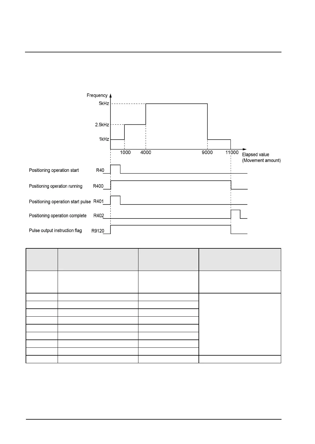
Time chart
Data table
Data
register
Setting item (Unit)
Example of sample
program
Settable range
DT400 Control code
H1000 0010
Absolute
CW/CCW
Set according to the control code
on the next page.
Set frequencies in the following
range.
K1 to K50000
Set target values in the following
range.
K-2,147,483,648 to
K+2,147,483,647
DT406 Frequency 2 (Hz) K2500
DT408 Target value 2 (pulses) K4000
DT414 Frequency 4 (Hz) K1000
DT416 Target value 4 (pulses) K11000
Note)
Each setting item occupies 2-word data registers.