2-3
RUN/PROG. mode switch
This switch is used to change the operation mode of PLC.
RUN (Position: Up) RUN mode :The program is executed and the operation begins.
PROG. (Position: Down) PROG. mode
:The operation stops. In this mode, programming can be
done using a tool software.
- Switching between RUN and STOP can be also performed by the remote operation from a
programming tool.
- When performing remote switching from the programming tool, the setting of the mode switch and the
actual mode of operation may differ. Verify the mode with the status indicator LED.
- Restart the power supply to operate in the mode set with the RUN/PROG. mode switch.
USB connector (Mini-USB B type (5-pin))
This connector is used to connect a programming tool.
A commercial USB cable (USB2.0 cable (A: miniB)) can be used.
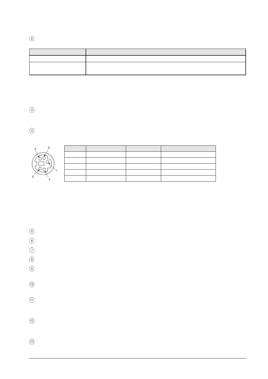
Tool port (RS232C)
This connector is used to connect a programming tool.
A commercial mini-DIN 5-pin connector is used for the tool port on the control unit.
→
←
→
- The followings are the default settings when the unit is shipped from the factory. The system register
should be used to change these.
Baud rate 9600bps
Char. Bit 8 bits
Parity check Odd parity
Stop bit 1 bit
Note) The unit number of the tool port should be set by the system register.
Input connector
Input status LEDs
Output connector
Output indicator LEDs
Power supply connector (24 V DC)
Supply 24 V DC. It is connected using the power supply cable (AFPG805) supplied with the unit.
COM port (RS232C or RS485)
Communication interface for connection with an external device such as a programmable display.
expansion hook
This hook is used to secure expansion units. The hook on the right side is also used for installation on
the flat-type mounting plate (AFP0804).
Right-side connector for FP0 expansion
This is used to connect the FP0-cum-FPΣ expansion unit installed on the right side of control unit to the
internal circuit. (The connector is located under the seal.)
DIN hook
This hook enables the unit to attach to a rail at a touch. It is also used to install the unit on the slim type
mounting plate (AFP0803).