8-58
8.5 PWM Output Function
8.5.1 Overview
PWM output function
With the F173 (PWMH) instruction, the pulse width modulation output of the specified duty ratio is
obtained.
System register setting
In order to use the PWM output function, it is necessary to set system register numbers no.402.
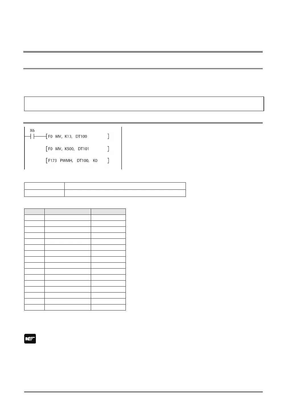
8.5.2 PWM Output Instruction F173
While X6 is on, a pulse with a period of 1 ms and duty
ratio of 50% is output from Y0 of specified channel
CH0.
When the program runs, the data table will be as
shown below.
Data table
Duty *2 : 50%
*1: Specify the control code by setting the K constant.
*2: Specify the duty by setting the K constant.
Duty: K0 to K999(1000 resolutions)
Note:
• If a value outside the specified range is written to the duty area while the instruction is being executed,
a frequency corrected to the maximum value is output. If written when instruction execution is started,
an operation error is occurred.