8-5
8.2 Function Specifications and Restricted Items
8.2.1 Specifications
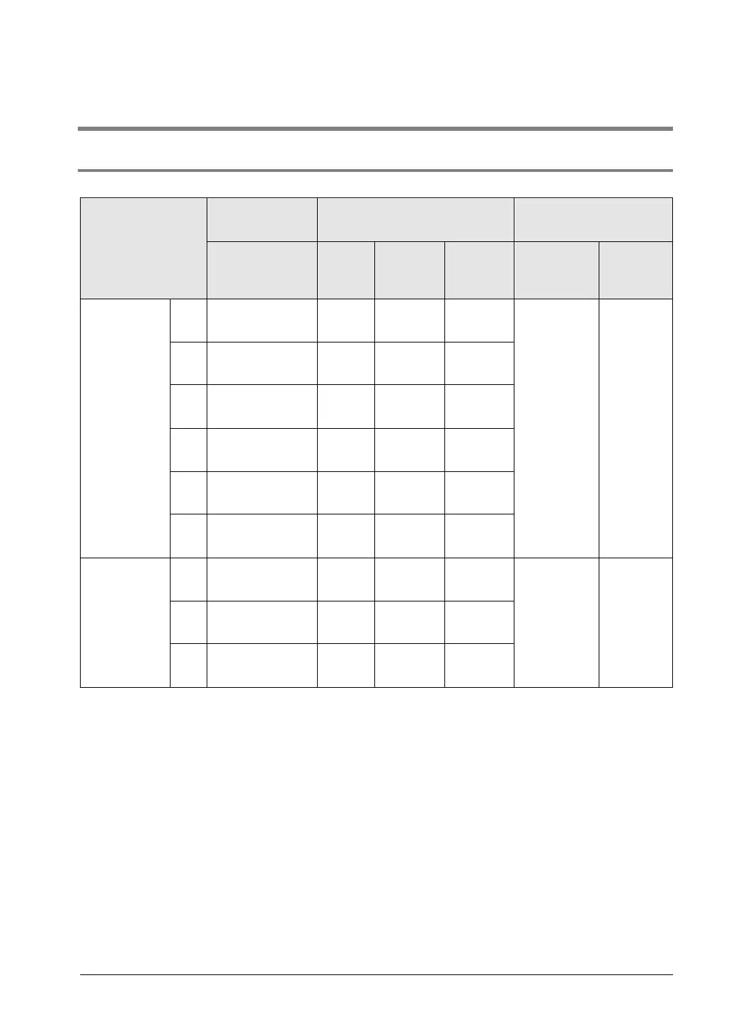
High-speed counter function
High-speed counter
channel No.
Input/output
contact No. being
Memory area being used
Performance
specifications
Input contact
number (value in
parenthesis is
Note1)
Control
flag
Elapsed
value area
Target
value area
Mini-mum
input pulse
width
Note2)
Maximum
counting
speed
[Single phase]
Incremental,
Decremental
CH0
X0
(X2)
R9110
DT90300
to
DT90302
to
10µs
6CH:
50 kHz
CH1
X1
(X2)
R9111
DT90304
to
DT90305
DT90306
to
DT90307
CH2
X3
(X5)
R9112
DT90308
to
DT90310
to
CH3
X4
(X5)
R9113
DT90312
to
DT90313
DT90314
to
DT90315
CH4
Note3)
X6
(None)
R9114
DT90316
to
DT90318
to
CH5
Note3)
X7
(None)
R9115
DT90320
to
DT90321
DT90322
to
DT90323
[2-phase]
2-phase input
One input,
Direction
distinction
CH0
X0
X1
R9110
DT90300
to
DT90302
to
25µs
1CH:
15kHz
2CH:
15kHz
3CH:
10kHz
CH2
X3
X4
(X5)
R9112
DT90308
to
DT90309
DT90310
to
DT90311
CH4
Note3)
X6
X7
R9114
DT90316
to
DT90318
to
Note1) The reset input X2 can be set to either CH0 or CH1. The reset input X5 can be set to either CH2
or CH3. The inputs X4 to X7 are also used for the home input of the pulse output function. It is necessary
to set how to use each input by system registers.
Note2) For information on minimum input pulse width, also refer to <8.3.3 Minimum Input Pulse Width>.
Note3) CH4 and CH5 cannot be used for the C10 type.
Note4) The maximum counting speed is the values when executing with the conditions of each item
(counting method or number of channels) only. These values are not available if executing the high-
speed counter match ON/OFF instruction, other pulse I/O process simultaneously or executing the
interrupt program.