8-6
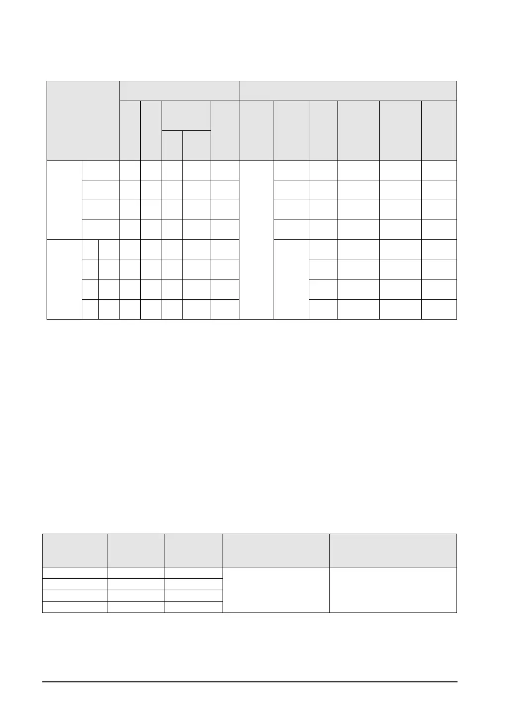
Pulse output function
High-speed counter
channel No.
Input/output contact number
Memory area used
CW
or
out-
put
or
sign
out-
put
Deviation
Home
input
Note3)
Near
home
input
Note2)
Position
control
starting
input
Note5)
Pulse
output
instruct
-tion
flag
Elapsed
value
area
Target
value area
Target
area for
match
on-off
C16
C32
T32
Indepen-
dence
CH0 Y0 Y1 Y6 Y8 X4
DT90052
<bit4>
X0 R9120
DT90400
DT90402
DT90404
CH1 Y2 Y3 Y7 Y9 X5 X1 R9121
DT90410
DT90412
DT90414
CH2 Y4 Y5 None
YA X6 X2 R9122
DT90420
DT90421
DT90422
DT90423
DT90424
DT90425
CH3 Y6 Y7 None
YB X7 X3 R9123
DT90430
DT90431
DT90432
DT90433
DT90434
DT90435
Linear
Interpola-
tion
CH0
X axis
Y0 Y1 Y6 Y8 X4
-
R9120
DT90400
DT90401
DT90402
DT90403
DT90404
DT90405
CH1
Y axis
Y2 Y3 Y7 Y9 X5 R9121
DT90410
DT90411
DT90412
DT90413
DT90414
DT90415
CH2
X axis
Y4 Y5 None
YA X6 R9122
DT90420
DT90421
DT90422
DT90423
DT90424
DT90425
CH3
Y axis
Y6 Y7 None
YB X7 R9123
DT90430
DT90432
DT90434
Note1) The pulse output function is available only for the transistor output type.
Note2) When using CH2 or CH3 with the C16 type, the deviation counter clear output cannot be used.
Also, Y6 and Y7 are also used for the pulse output of CH3 and the deviation counter clear of CH0
or CH1, and they can be used only as one of the outputs.
Note3) The home inputs X4 to X7 are also used for the input of the high-speed counter. It is necessary to
set how to use each input by system registers.
Note4) The near home input is used by assigning an arbitrary contact and operating the bit 4 of the
special data register DT90052 with the instruction (F0).
Note5) The home control start input is used for the trigger to start the position control when using the
JOG positioning instruction (F171). It is used by specifying X0 to X3 with the system register or
assigning an arbitrary contact and operating the bit 6 of the special data register DT90052 with
the instruction (F0).
Note6) For the linear interpolation, CH0 and CH1 or CH2 and CH3 are used in combination.
Note7) The output frequency is the value only when the conditions of each item (such as output method
or No. of channels) are executed. This is the value when the pulse input/output process is not
simultaneously performed or interrupt program is not executed.
PWM output function
High-speed
counter
Output
contact No.
Pulse output
instruction
Output frequency Duty
CH0 Y0 R9120
6 Hz to 4.8 kHz
0.0% to 99.9%
(Resolution: 1000)
CH1 Y2 R9121
CH2 Y4 R9122
CH3 Y6 R9123
Note) The PWM output function is only available with the transistor output type.