7-39
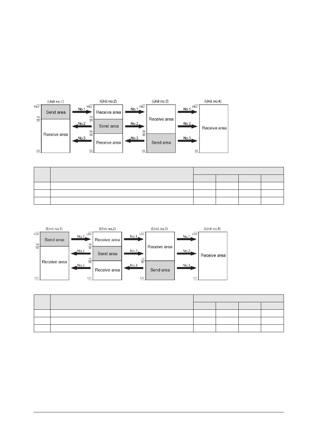
Example of allocation
The areas for PC(PLC) link are divided into send areas and receive areas. The link relays and link
registers are sent from the send area to the receive area of a different PLC. Link relays and link registers
with the same numbers as those on the transmission side must exist in the receive area on the receiving
side.
For PC(PLC) link 0
Link relay allocation
System registers
No. Name
Setting for various units
40 Range of link relays used 64 64 64 64
Starting No. of word for link relay transmission
43 Link relay transmission size 20 20 24 0
Note) No.40 (range of link relays used) must be set to the same range for all the units.
Link register allocation
System registers
No. Name
Setting for various units
Range of link registers used
44 Starting No. for link register transmission 0 40 80 0
Link register transmission size
Note) No.41 (range of link registers used) must be set to the same range for all the units.
When link areas are allocated as shown above, the No.1 send area can be sent to the No.2, No.3 and
No.4 receive areas. Also, the No.1 receive area can receive data from the No.2 and No.3 send areas.
No.4 is allocated as a receive area only, and can receive data from No.1, No.2 and No.3, but cannot
transmit it to other stations.